
Exhaust gas apparatus of an internal combustion engine

a technology of exhaust gas apparatus and internal combustion engine, which is applied in the direction of mechanical apparatus, engine components, machines/engines, etc., can solve the problems of reducing the efficiency achieved by charge stratification, limiting its use in certain markets, and additional cost disadvantages in comparison to conventional exhaust gas posttreatment systems, etc., to achieve wide operating range and effective

Inactive Publication Date: 2014-12-09
ROBERT BOSCH GMBH
View PDF15 Cites 1 Cited by
  • Summary
  • Abstract
  • Description
  • Claims
  • Application Information

AI Technical Summary

Benefits of technology

[0008]The object of the invention is to furnish a selective catalytic preparation of exhaust gases from an internal combustion engine, in particular an internal combustion engine with direct gasoline injection, which avoids the aforementioned disadvantages and enables the most effective possible denitrification of the exhaust gases over a wide operating range.
[0009]To that end, an exhaust gas apparatus of an internal combustion engine, in particular an internal combustion engine with direct gasoline injection, having at least one selective catalytic converter, is proposed in which it is provided that the selective catalytic converter is preceded by a first catalytic converter. The first catalytic converter preceding the selective catalytic converter removes the hydrocarbon components from the exemplary embodiment, which are harmful to the selective catalytic converter, and at λ=1, it also removes CO and NOx components, so that good exhaust gas cleaning is attained from the very outset. The first catalytic converter is especially advantageously embodied as a three-way catalytic converter of known construction, but with a comparatively compact volume. In known three-way catalytic converters, a very good conversion precisely of hydrocarbon components, CO components, and nitrogen oxides can be attained in an operating range in which λ is approximately =1. With a relatively compact structure of this first catalytic converter, fast thorough warming can also be attained, so that the onset of effectiveness of the first catalytic converter is very fast.
[0012]An embodiment in which a volume-adjusting and closure device is connected parallel to a series circuit of the first catalytic converter and the selective catalytic converter is preferred. The volume-adjusting and closure device serves as a kind of bypass to carry the volumetric exhaust gas stream from the series circuit (formed of the first catalytic converter and the selective catalytic converter), or parallel to it and past it, and preferably the volume-adjusting and closure device permits a continuously variable adjustment of the volumetric stream of exhaust gas, so that the volumetric stream of exhaust gas can be guided entirely through the series circuit, or both through the series circuit and past it in volumetric stream proportions to be predetermined. It can thus be prevented that the first catalytic converter, also in the form of a cold start catalytic converter preferably disposed near the engine for very fast thorough warming, will overheat in certain load states, in which a very high volumetric stream of exhaust gas at high temperature occurs; it can also be prevented that the selective catalytic converter, following the first catalytic converter, will be burdened in operating states in which that is unnecessary.
[0014]In another embodiment, the first catalytic converter experiences the flow through it of the entire exhaust gas stream or volumetric exhaust stream from the engine. In a different way from the exemplary embodiments described above, the disposition of the first catalytic converter as a cold start catalytic converter is such that it always experiences the entire exhaust gas stream from the engine, or in other words is not at least partly taken out of the volumetric stream of exhaust gas as a result of a bypass of the volume-adjusting and closure device. In this way, it is possible to design the second catalytic converter (that is, the main catalytic converter in the known three-way catalytic converter technique) as substantially smaller and more economical, and furthermore, installation space can advantageously be economized on, space that would have been necessary for a large three-way catalytic converter that is usual in the prior art. Here the first catalytic converter already reduces a large proportion of the emissions, so that now the second catalytic converter has to convert only lesser proportions of hydrocarbon, carbon monoxide and NOx components. At very high exhaust gas temperatures, however, adequate temperature resistance of the first catalytic converter must be provided for; unwanted overheating of the first catalytic converter can be counteracted for instance by active component protection provisions, such as enriching the mixture; at the same time, heat dissipation provisions known from the prior art can be considered, which can optionally be turned on and off again as needed, for instance as a function of a temperature of the first catalytic converter, which is intended to be detected by suitable devices. To the extent that such provisions as mixture enrichment are employed, this should be preferably provided in operating states of the kind in which the mixture enrichment is usual in the prior art any way, so as to protect other components, for instance, such as a pipe elbow or exhaust gas turbocharger, against overheating. Since in contrast to the embodiments described above, no branching in the exhaust tract has to be provided upstream of the first catalytic converter, the first catalytic converter can be installed quite close to the engine, so that not only extremely fast heating up, even in cold starting, but also higher operating temperatures, even in the low load range, can be attained.
[0017]In a further preferred embodiment, the first catalytic converter has a reaction layer, which comprises the elements platinum or rhodium, or a combination or connection of the two elements, and / or has these elements and / or compounds of these elements. In this embodiment, it can very advantageously be ensured that the NO2 proportion in the lean mode is raised sufficiently to allow the selective catalytic converter to become effective quite quickly. Unlike the conventional three-way catalytic converter coating (palladium / rhodium, for instance) known in the prior art, here a reaction layer with the elements of platinum and / or rhodium is used, which advantageously enables raising the NO2 proportion in the lean mode upstream of the selective catalytic converter.

Problems solved by technology

However, the lean mixture composition prevents a desired high reduction of nitrogen oxides in the three-way catalytic converter, and for that reason, to achieve more-favorable exhaust gas values, special NOx reservoir systems and deNOx catalytic converters are used.
The prerequisite is low-sulfur fuel, but it is not extensively available worldwide, which restricts its use in certain markets.
Moreover, the advantage in efficiency attained by charge stratification is reduced by the necessary regeneration of the deNOx catalytic converter, and there are additional cost disadvantages in comparison to conventional exhaust gas posttreatment systems.
However, in Otto engines, especially those with direct gasoline injection, such systems cannot be used for lack of high-temperature resistance of the selective catalytic converters.
Moreover, the selective catalytic process is impeded vulnerably by the hydrocarbons that are present in the exhaust gases from Otto engines.

Method used


Image

  • Exhaust gas apparatus of an internal combustion engine
  • Exhaust gas apparatus of an internal combustion engine
  • Exhaust gas apparatus of an internal combustion engine

Examples


Embodiment Construction

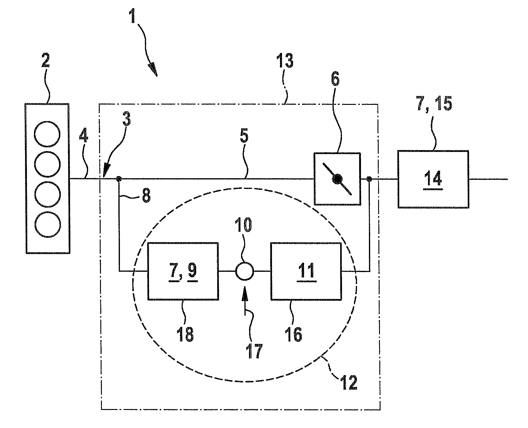
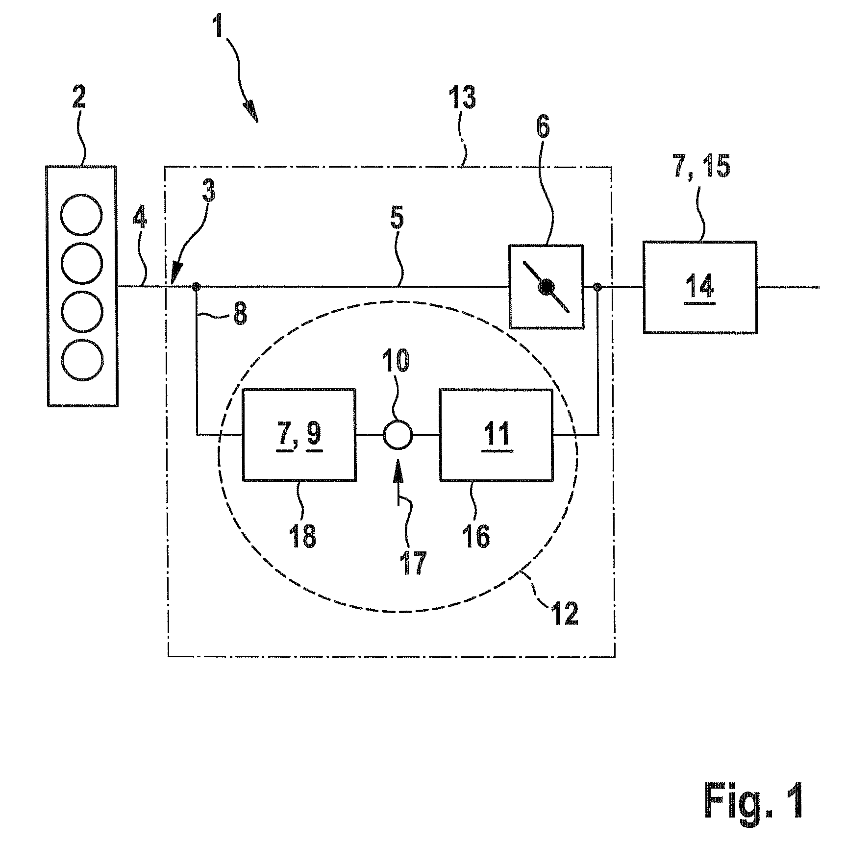
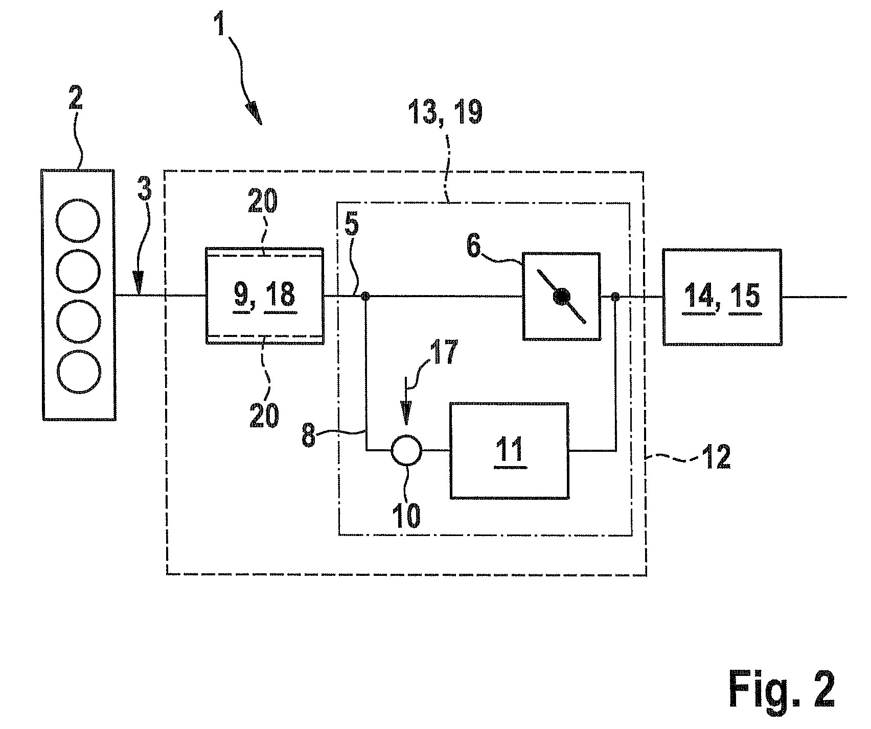
[0022]FIG. 1 shows an exhaust gas apparatus 1 of an internal combustion engine 2 in a symbolic, simplified illustration.

[0023]In a region 3 near the engine, an exhaust tract 4 is divided into a main branch 5, in which a volume-adjusting and closure device 6 is disposed, and a selective branch 8, which connected in series has a first catalytic converter 9, downstream of it an inlet point 10 for reducing agent, not shown, and the selective catalytic converter 11 following it downstream. The first catalytic converter 9 is a three-way catalytic converter 7. The series circuit 12, embodied of the first catalytic converter 9, the inlet point 10, and the selective catalytic converter 11, discharges downstream of the volume-adjusting and closure device 6 into the main branch 5, and with the volume-adjusting and closure device 6, it forms a parallel circuit 13. Downstream of the parallel circuit 13 is a second catalytic converter 14, which is embodied as a main catalytic converter 15 and whi...


PUM


Abstract

The invention is an exhaust gas apparatus of an internal combustion engine, in particular of an internal combustion engine with gasoline direct injection. The exhaust gas apparatus includes at least one selective catalytic converter. It is provided that a first catalytic converter is positioned upstream of the selective catalytic converter. The invention also provides a method for the purification of exhaust gas of an internal combustion engine, in an internal combustion engine with gasoline direct injection, for use in such an exhaust gas apparatus. In the method the selective catalytic converter is preceded by a first catalytic converter disposed upstream therefrom.

Description

CROSS-REFERENCE TO RELATED APPLICATION[0001]This application is a 35 USC 371 application of PCT / EP2009 / 050655 filed on Jan. 21, 2009.BACKGROUND OF THE INVENTION[0002]1. Field of the Invention[0003]The invention relates to an exhaust gas apparatus of an internal combustion engine, in particular an internal combustion engine with direct gasoline injection, having at least one selective catalytic converter. The invention further relates to a method for cleaning the exhaust gas from an internal combustion engine, in particular an internal combustion engine with direct gasoline injection, in particular for use in an exhaust gas apparatus.[0004]2. Description of the Prior Art[0005]The fuel consumption of Otto engines, especially Otto engines with direct gasoline injection, can be reduced markedly in the partial-load range with the aid of combustion with air excess and by means of charge stratification. Pronounced advantages in combustion in the lowest load range (to some extent above 30%)...

Claims


Application Information

Patent Timeline
Patent Type & Authority Patents(United States)
IPC IPC(8): F01N3/20F01N3/00F01N3/10F01N13/00
CPCF01N3/2066F01N2610/02F01N13/011Y02T10/24F01N2250/00F01N13/009F01N2570/10Y02T10/22Y02T10/12
Inventor RAATZ, THORSTEN
Owner ROBERT BOSCH GMBH
Learn More