
Metal-backed plain bearing

a technology of metal-backed plain bearings and bearings, which is applied in the field of plain bearings and materials, can solve the problems of difficult or undesirable use of externally supplied lubricants, bronze metallic interlayers and steel backings, and achieve the effect of similar bearing strength and lining adhesion

Active Publication Date: 2015-01-13
GGB U S HOLDCO LLC
View PDF43 Cites 7 Cited by
  • Summary
  • Abstract
  • Description
  • Claims
  • Application Information

AI Technical Summary

Benefits of technology

The patent describes a new type of bearing that eliminates the need for a porous bronze interlayer while maintaining the same level of strength and adhesion as a three-layer bearing. The bearing is made of a resin matrix filled with fluoropolymer, graphite, and other particles of an additive material that can be attached to a backing material. The specific selection and mix of fillers with the resin matrix provides the desired blend of bearing properties such as wear resistance, fatigue and erosion resistance, and low friction while maintaining sufficient flexibility for being formed into flanged cylindrical geometries without detriment to the adherence of the lining to the backing.

Problems solved by technology

Each of these bearings can be useful in dry applications where the use of externally supplied lubricants may be difficult or undesirable.
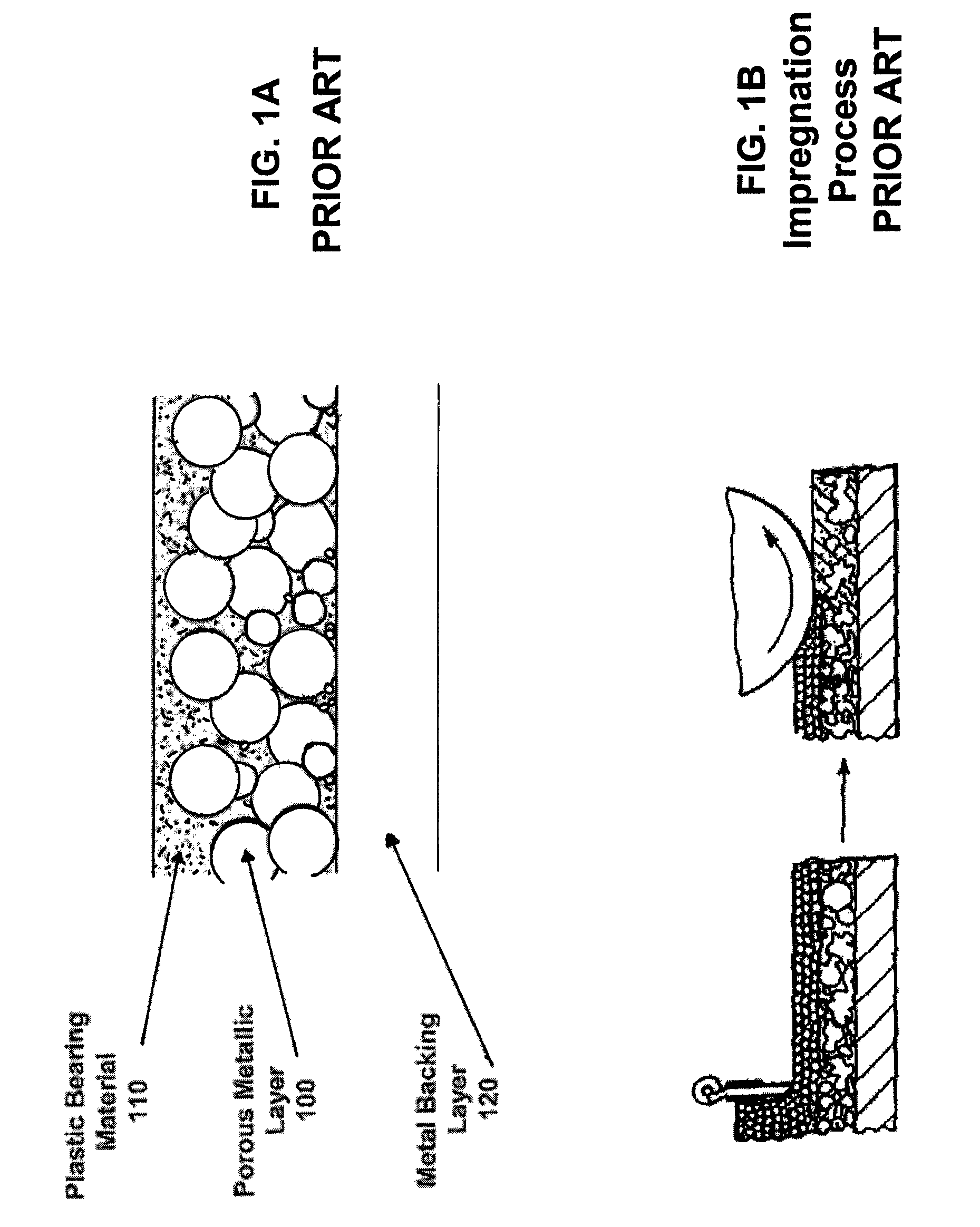
Without the porous metallic layer, the polymer material will not directly fuse with the metal backing as to provide sufficient strength, adherence or provide the necessary tribological properties, such as wear resistance, fatigue resistance, erosion resistance, low friction and self lubricity for use in highly loaded dry environments.
A bronze metallic interlayer and steel backing can be susceptible to corrosion upon contact with some chemicals and moisture, even when commercially available anti-corrosion coatings such as zinc-nickel or tin flash are applied to the metal backing.

Method used


Image

  • Metal-backed plain bearing
  • Metal-backed plain bearing
  • Metal-backed plain bearing

Examples


Embodiment Construction

[0021]Reference will now be made in detail to embodiments of the invention, one or more examples of which are illustrated in the accompanying attachments. Each example is provided by way of explanation of the invention, not as a limitation of the invention. It will be apparent to those skilled in the art that various modifications and variations can be made in the present invention without departing from the scope or spirit of the invention. For example, features illustrated or described as part of one embodiment of the invention can be used on another embodiment to yield a still further embodiment. Thus, it is intended that the present invention cover such modifications and variations that come within the scope of the invention.

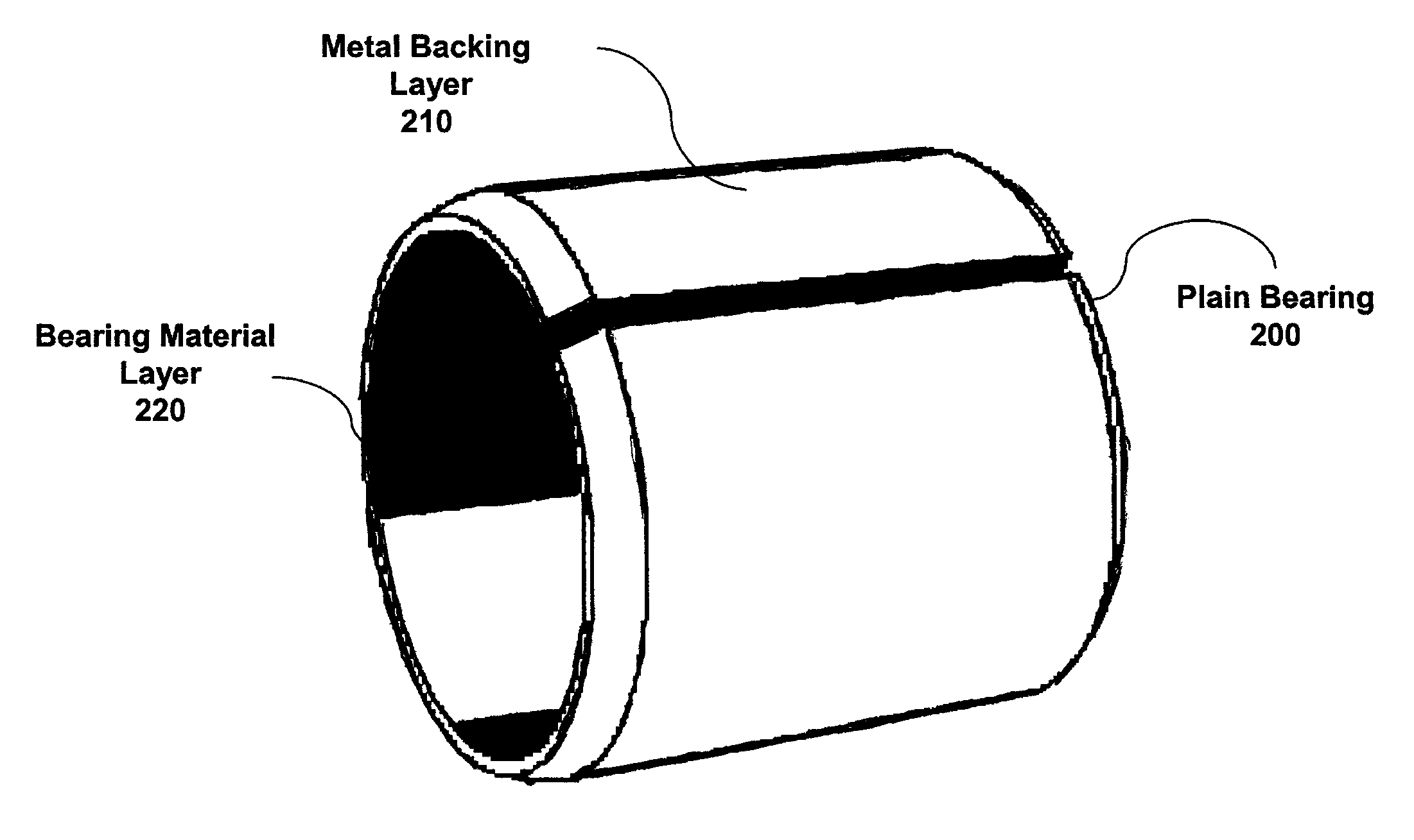
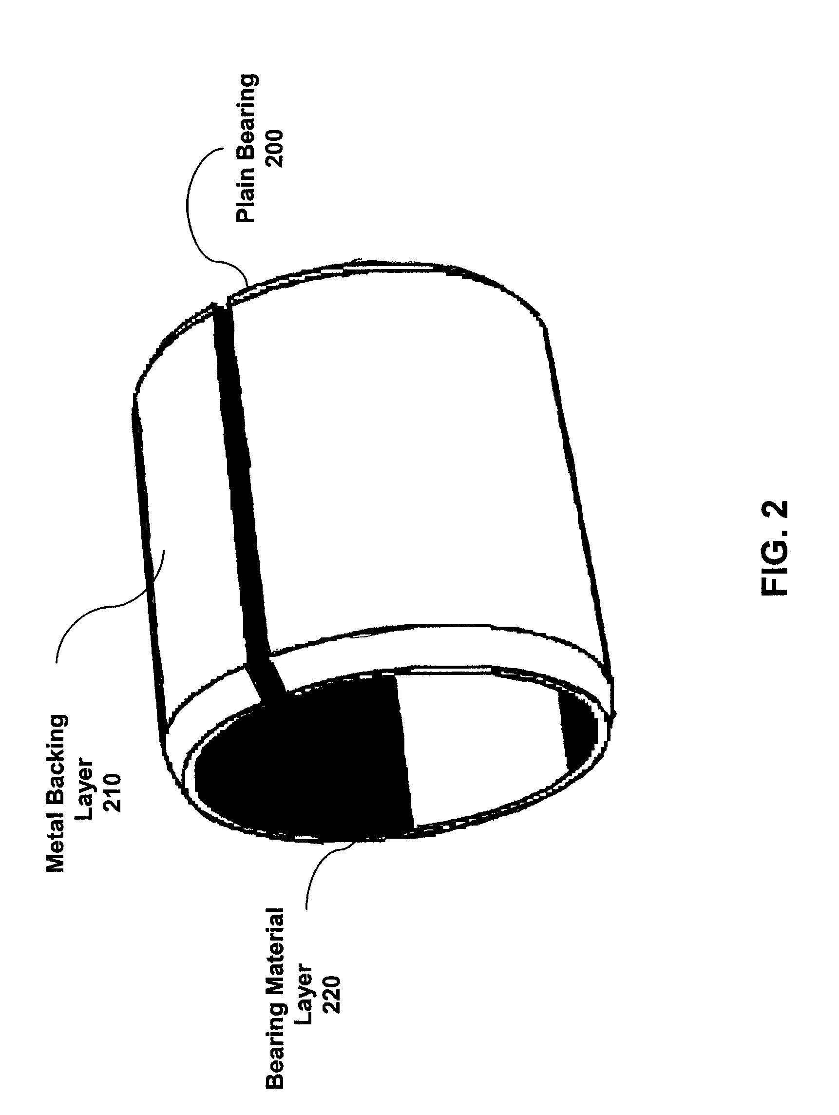
[0022]FIG. 2 shows a plain bearing 200 having a metal backing layer 210 and a bearing material layer 220. The bearing material layer 220 can be a continuous consolidated structure comprising a curable resin mixed with a combination of fillers and discrete pa...


PUM

PropertyMeasurementUnit
adhesionaaaaaaaaaa
frictionaaaaaaaaaa
rigidityaaaaaaaaaa

Abstract

A bearing comprises a resin matrix filled with fluoropolymer, graphite, and other discrete particles of an additive material that is attached to a backing material. The specific selection and mix of fillers with the resin matrix provides the desired blend of bearing properties such as wear resistance, fatigue and erosion resistance and low friction whilst maintaining sufficient flexibility for being formed into flanged cylindrical geometries without detriment to the adherence of the lining to the backing. A method for manufacturing a bearing comprises depositing to a backing material a fluid polymer bearing material comprised of a resin matrix filled with fluoropolymer, various fillers, and discrete particles of an additive to form a continuous consolidated bearing material, and curing the lining material to bond the lining material onto the backing material.

Description

CROSS-REFERENCE TO RELATED APPLICATIONS[0001]This application claims the priority benefit of U.S. Provisional Patent Application No. 60 / 935,678, entitled “METAL-BACKED PLAIN BEARING,” and filed on Aug. 24, 2007, the entire disclosure of which is incorporated herein by reference.BACKGROUND OF INVENTION[0002]1. Field of Invention[0003]The present invention relates generally to the field of plain bearings and materials for use therein. More specifically, the present invention relates to a low friction resin-based surface applied to a metal backing to form a high performance, self lubricated plain bearing.[0004]2. Description of the Related Art[0005]Conventional metal polymer plain bearings with polymer based sliding surfaces are typically composed of two-layer or three-layer composite bearing structures. Both forms rely on a metal backing to provide rigidity and allow the material to be formed into the appropriate shape, more commonly a cylinder. The metal polymer two-layer bearing mat...

Claims


Application Information

Patent Timeline
Patent Type & Authority Patents(United States)
IPC IPC(8): F16C33/20F16C33/16
CPCF16C33/20F16C33/201F16C33/205F16C33/208Y10S384/9071Y10S384/908F16C17/02F16C33/046F16C2202/50F16C2202/52F16C2208/02F16C2208/30F16C2208/82F16C2208/86F16C2223/30Y10T29/49636Y10T29/49647Y10T29/49668Y10T29/4967Y10T29/49671Y10T29/49677B05D1/30B05D1/42B23P15/003F16C33/203
Inventor HARDGRAVE, ADRIANCHANTOSSEL, RAPHAEL
Owner GGB U S HOLDCO LLC
Learn More