Drive device for electric vehicle

a technology for electric vehicles and drive devices, which is applied in the direction of electric propulsion mounting, transportation and packaging, and gearing, etc. it can solve the problems of deterioration of occurrence of deterioration of the durability of the bearings, so as to suppress the rotational noise of the bearings and the rotational accuracy of the input sha

Inactive Publication Date: 2015-01-13
NTN CORP
View PDF22 Cites 8 Cited by
  • Summary
  • Abstract
  • Description
  • Claims
  • Application Information

AI Technical Summary

Benefits of technology

[0020]Since both the flanges are securely engaged and integrated with each other by the above-described bridge, the support stiffness of the support pin such as the pinion pin, both end portions of which are coupled to both the flanges, is increased. Moreover, by providing the bridge at multiple locations of equally spaced positions in a circumferential direction of the flange, the rotation of the output member becomes smooth, and the rotational accuracy of the input shaft and the rotor of the electric motor fitted and secured to the input shaft is improved.
[0021]As so far described, since the present invention is configured such that the pair of bearings supporting the input shaft of the speed reduction unit are attached together to the output member of the speed reduction unit, it is possible to prevent eccentric load from acting on the bearings. As a result of that, the rotational accuracy of the input shaft and the durability of the bearings are improved, and further rotational noise of the bearings is suppressed.

Problems solved by technology

For this reason, a problem exists in that eccentric load is likely to act on the inboard side bearing and the outboard side bearing, thereby causing deterioration of the rotational accuracy of the input shaft, deterioration of the durability of the bearings, and occurrence of rotational noise of the bearings.

Method used


Image

  • Drive device for electric vehicle
  • Drive device for electric vehicle
  • Drive device for electric vehicle

Examples


embodiment 1

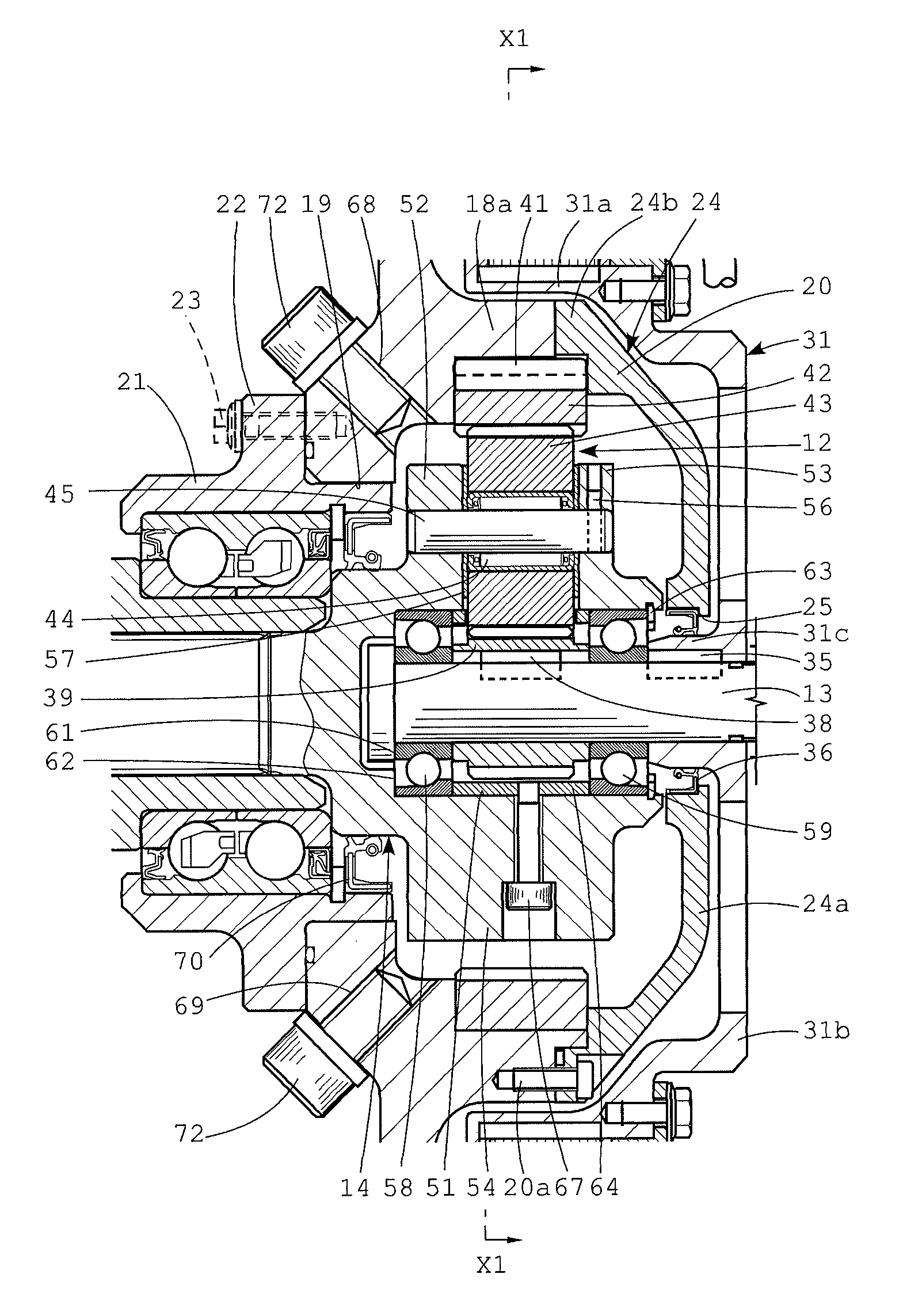
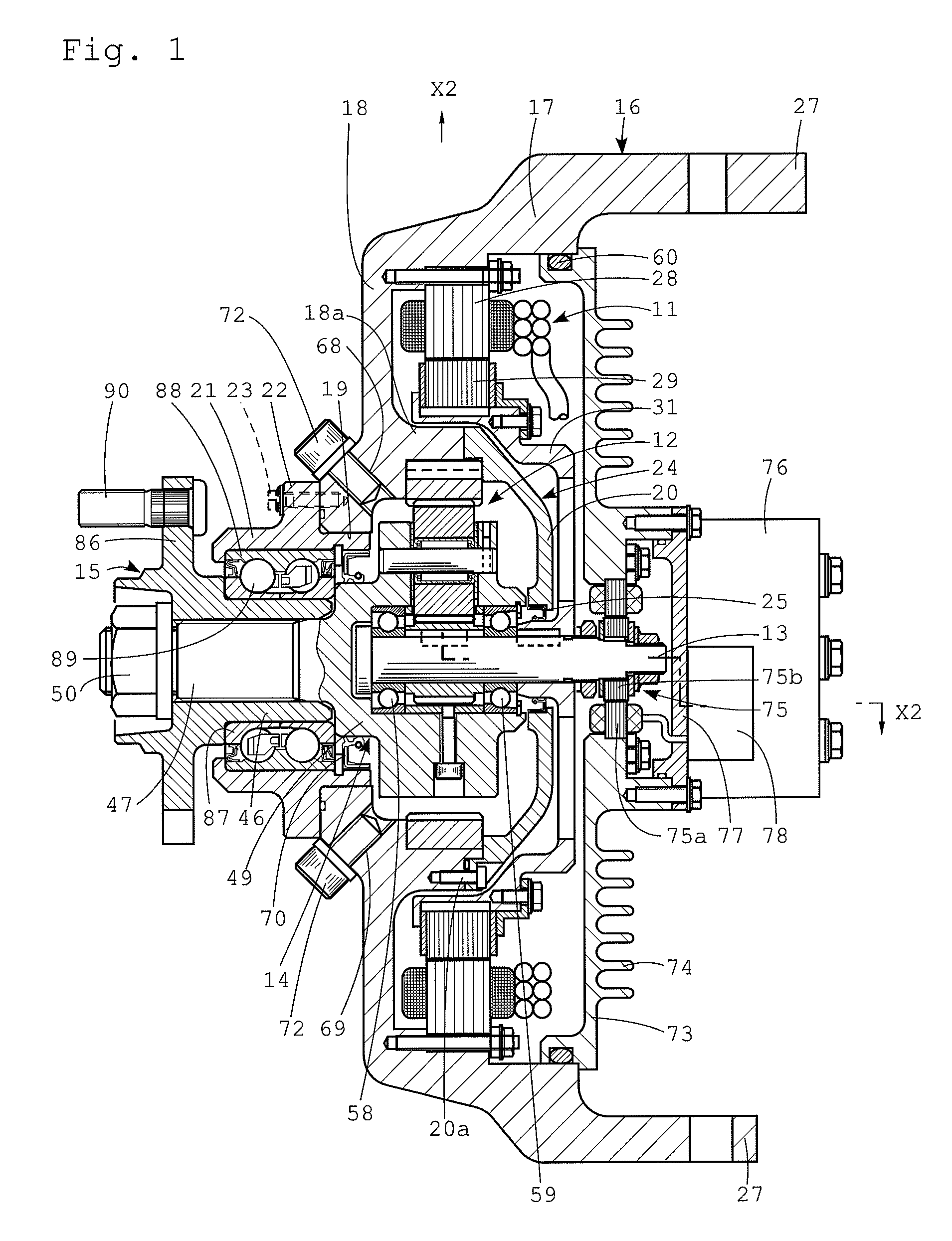
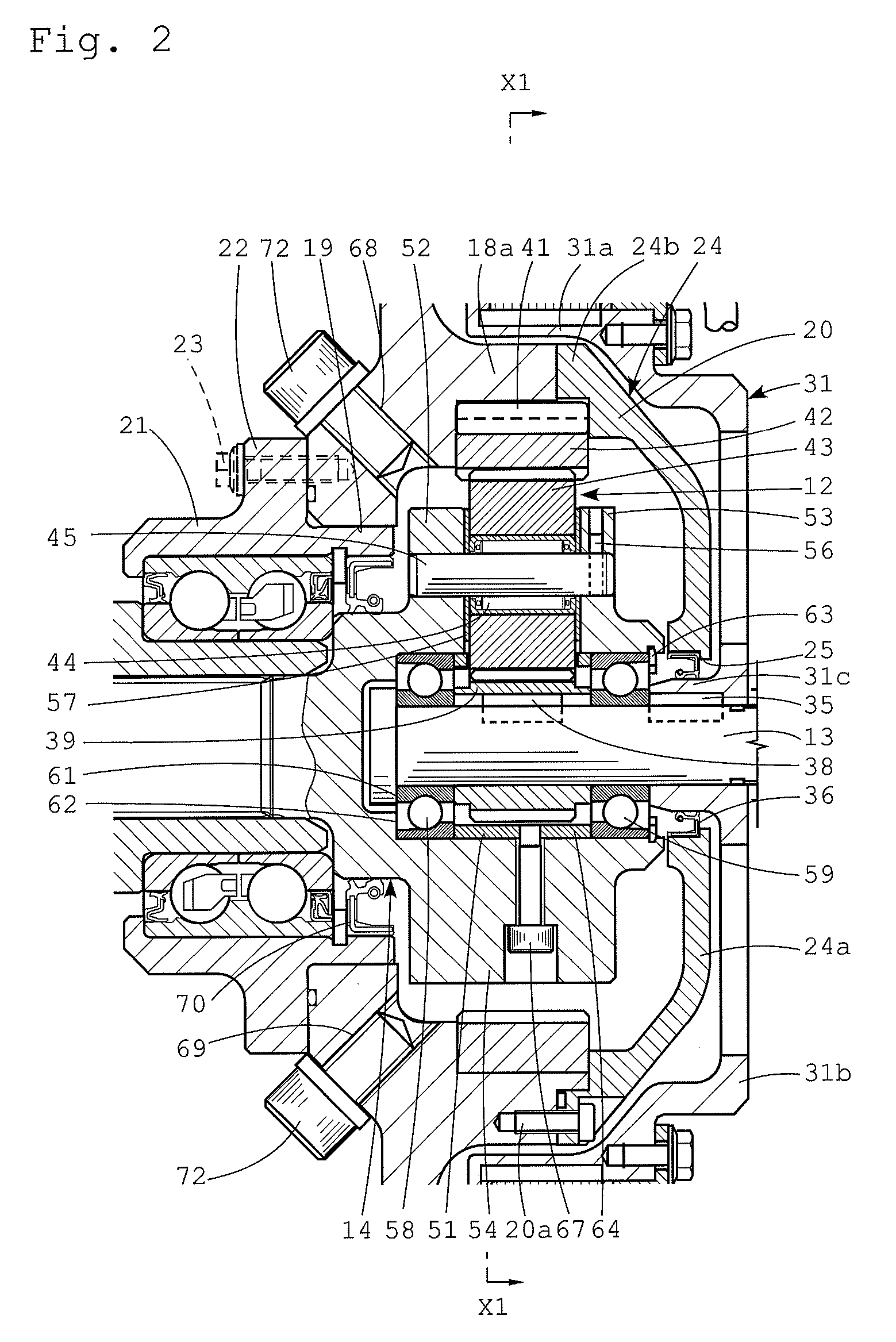
[0034]A drive device for an electric vehicle relating Embodiment 1 includes, as principal components, an electric motor 11, a speed reduction unit 12 which is driven by the output power of the electric motor 11, a hub unit 15 which is rotated by an output member 14 coaxial with an input shaft 13 of the speed reduction unit 12, and a housing 16 which accommodates the electric motor 11 and the speed reduction unit 12, as shown in FIG. 1.

[0035]The above-described housing 16 includes a cylindrical portion 17 and a front end portion 18 in the radial direction, which is provided at the front end of the cylindrical portion (the end portion of an outboard side, or an end portion on the left side of the figure). A central portion of the front end portion 18 is opened, and a rear end portion of an outer member 21 of the hub unit 15 is fitted into an opening portion 19 so that a flange 22 is secured to the front end portion 18 with a bolt 23.

[0036]A partition base portion 18a, which is concent...

embodiment 2

[0081]Embodiment 2 shown in FIG. 7 differs in the configuration of the hub unit 15 compared with the above-described Embodiment 1. That is, the flange 22 of the outer member 21 of the hub unit 15 in this case is formed to have a larger diameter than that of the flange 22 (see FIG. 1) of the above-described Embodiment 1.

[0082]A flange cylindrical portion 32 projecting in the axial direction is provided in the inner side surface of the flange 22 with a larger diameter. The flange cylindrical portion 32 extends over an outer radial surface of the flange 52 on the outboard side of the output member 14. The flange cylindrical portion 32 is fitted to an inner radial surface of the opening hole 19 of the front end portion 18 of the housing 16.

[0083]Since, compared with the case of Embodiment 1, the opening hole 19 is formed to have a large inner diameter, it is easy to fabricate the partition 24 which is integrated with the front end portion 18, in the case of this Embodiment 2. For this r...

embodiment 3

[0089]Embodiment 3 shown in FIGS. 8 to 10 differs from Embodiment 1 in the configurations of the hub unit 15, the rotation angle sensor 75, the power supply terminal box 76, and the connector insertion portion 78.

[0090]That is, the hub unit 15 in this case is formed such that the flange 22 of the outer member 21 has a larger diameter than in the case of Embodiment 1. Since, for this reason, the opening hole 19 of the front end portion 18 of the housing 16 is formed to have a larger inner diameter as in the case of Embodiment 2, it is possible to form the partition 24 integrally with the front end portion 18.

[0091]The ball 89a on the outboard side constituting the hub bearing is placed between the track groove provided in the outer radial surface of the inner member 46 and the track groove provided in the inner radial surface of the outer member 21. Further, the ball 89b on the inboard side is placed between the track grove provided in the outer radial surface of the output member 14...


PUM


Abstract

An object of the present invention is to achieve improvements in the rotational accuracy of the input shaft and the durability of the bearings, and suppression of rotational noise, by improving the support structure of the input shaft of the speed reduction unit. Provided is a drive device for an electric vehicle, including: an electric motor; a speed reduction unit including an input shaft driven by output of the electric motor; and a hub unit rotationally driven by an output member of the speed reduction unit, wherein the input shaft of the speed reduction unit is supported by bearings provided at two locations in an axial direction, the drive device for an electric vehicle being configured such that the bearings at the two locations are attached together to the output member.

Description

TECHNICAL FIELD[0001]The present invention relates to a drive device for an electric vehicle including an electric motor as a drive source, and particularly to a drive device for an electric vehicle of an in-wheel motor type.[0002]A conventionally known drive device for an electric vehicle of an in-wheel motor type is made up of an electric motor, a speed reduction unit to which the output of the electric motor is inputted, and a hub unit which is rotated by the speed-reduced output of the speed reduction unit (Patent Literature 1).[0003]In the drive device for an electric vehicle disclosed in Patent Literature 1, an electric motor is disposed outside the speed reduction unit in the radial direction, and the speed reduction unit in which planetary gear-type units are disposed in two stages in the axial direction is used. The reason why the speed reduction unit is disposed in two stages is for the purpose of increasing the speed reduction ratio.[0004]A typical configuration of a spee...

Claims


Application Information

Patent Timeline
Patent Type & Authority Patents(United States)
IPC IPC(8): F16H3/72B60K1/00B60K7/00B60K17/04F16H57/00F16H57/08H02K7/116H02K24/00
CPCH02K7/116H02K24/00B60K7/0007B60K17/046B60K1/00F16H57/0037F16H57/082Y02T10/641B60K2007/0038B60K2007/0092Y02T10/64
Inventor SUZUKI, MINORUMAKINO, TOMOAKI
Owner NTN CORP
Why Eureka
Try Eureka