Quick-change system and operating method for a container processing machine

a container processing machine and quick-change technology, applied in the field of quick-change system and operating method of container processing machine, can solve the problems of high rejection rate, inability to guarantee the preform of the heating module, and damage accordingly, and achieve the effect of high level of operation reliability

Active Publication Date: 2015-01-27
KRONES AG
View PDF14 Cites 3 Cited by
  • Summary
  • Abstract
  • Description
  • Claims
  • Application Information

AI Technical Summary

Benefits of technology

[0008]The basis of the disclosure is formed by one aspect of improving a quick-change system of the type mentioned at the beginning to the effect that the danger of damage due to machine elements that are incorrectly positioned after an exchange is also minimized during the machine's operating sequence, and by an operating method for a container processing machine that guarantees a high level of operational reliability in spite of the system-related disadvantages of the quick-change system.
[0009]In spite of the quick-change system that allows short exchange times, the second securing unit guarantees that, e.g., in the event of an uncontrolled loosening of the machine element during the operating sequence, the machine element does not completely detach from the holder in an uncontrolled manner or move so far that it causes damage during the operating sequence. The second securing unit is executed and positioned in such a way that a machine element that initially loosens in an uncontrolled manner is immediately brought back under control and localized in the securing position and can no longer loosen further. It remains positioned in the securing position in such a way that no damage or no significant damage can result in the machine. Initially the second securing unit ensures that a loosened machine element at least does not initially reduce the operational reliability.
[0010]According to the method, the second securing unit is used in order to allow a defined detection of a loosened machine element and, upon detection of the securing position, to evaluate it for initiating or requesting a corrective action. The second securing unit and the securing position for the machine element that this securing unit sets up can namely represent a danger for the operating sequence, because proper product processing can only be reliably guaranteed in the target position, and damage would accordingly be caused in the event of an operating sequence that lasted a longer time. Countermeasures can be taken for this, however. Detection is simple and can be carried out with simple detection means, because only the securing position needs to be considered, and it is not necessary to scan each uncontrolled change in the machine element's position. The second securing unit is provided, so to speak, combinatorially in the quick-change system for safety reasons, in order, in the event of a fault, to prevent the machine element from becoming completely detached from the holder or from protruding too far out of the holder, and this second securing unit is used according to the method as a precondition for simple and reliable detection and possibly for remedying a fault that increases the operational hazard. This is particularly expedient in the heating module of a container blow-molding machine, for example, for fitting parts on a conveyor chain for transporting the preforms through the heating module, because fitting parts that have become completely detached or that project too far could permanently damage heating devices, and above all the proper processing of the preforms in the heating module could no longer be guaranteed, instead leading to an expensive rejection rate. However this operating method is also expedient, for example, for molding shells or mold bottoms of blow molds in the blow-molding machine that can be exchanged with a fast-change system in short exchange times.

Problems solved by technology

The second securing unit and the securing position for the machine element that this securing unit sets up can namely represent a danger for the operating sequence, because proper product processing can only be reliably guaranteed in the target position, and damage would accordingly be caused in the event of an operating sequence that lasted a longer time.
This is particularly expedient in the heating module of a container blow-molding machine, for example, for fitting parts on a conveyor chain for transporting the preforms through the heating module, because fitting parts that have become completely detached or that project too far could permanently damage heating devices, and above all the proper processing of the preforms in the heating module could no longer be guaranteed, instead leading to an expensive rejection rate.
In particular, the securing position prevents the machine element from being able to move in an uncontrolled manner beyond the securing position into a dangerous position or from being able to detach completely from the holder, for instance, in the face of vibrations caused during operation or forces exercised thereupon during the operating sequence.

Method used


Image

  • Quick-change system and operating method for a container processing machine
  • Quick-change system and operating method for a container processing machine
  • Quick-change system and operating method for a container processing machine

Examples


Embodiment Construction

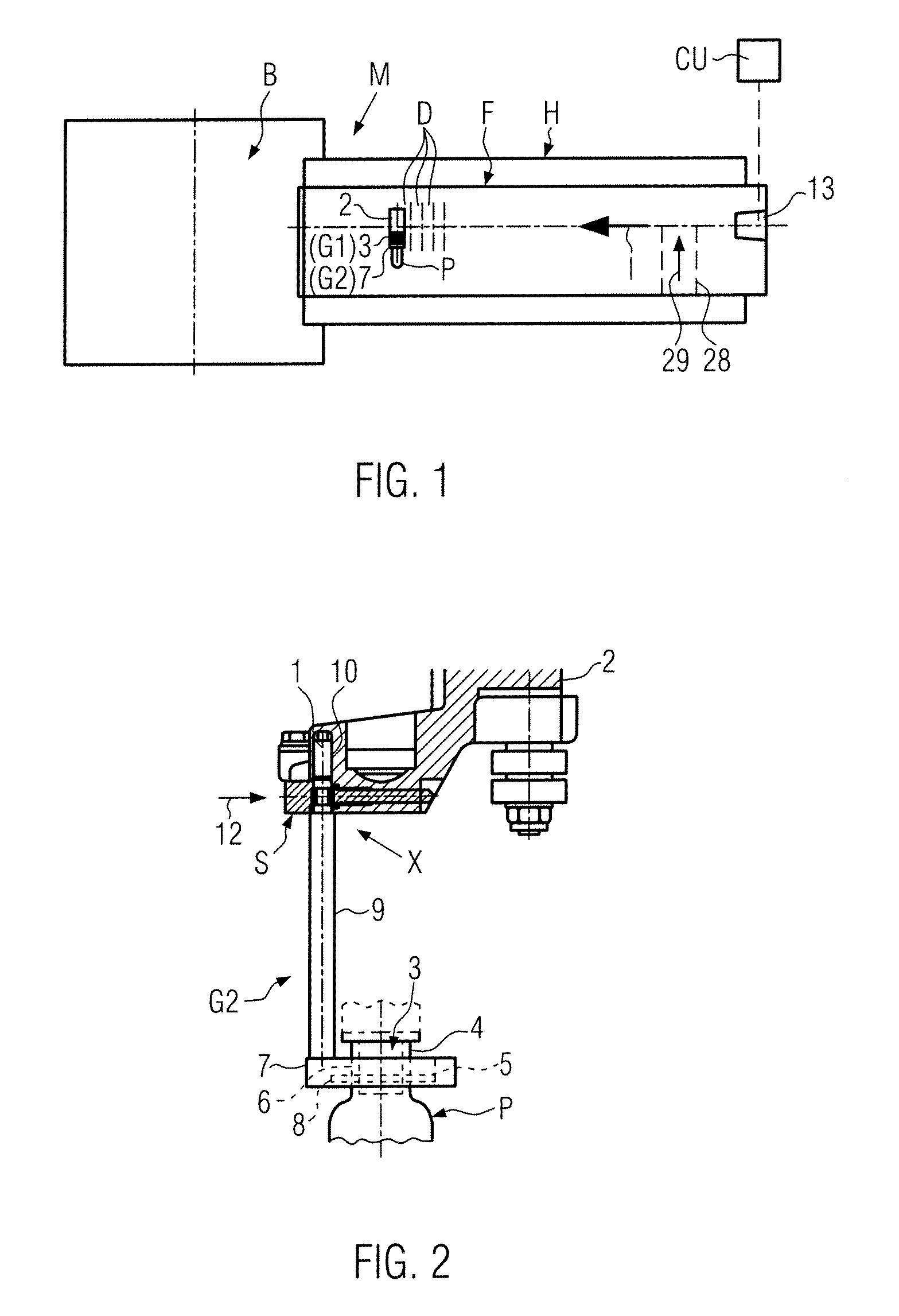
[0031]FIG. 1 schematically illustrates, as a non-restrictive example, a blow-molding machine M for containers, for example, a stretch blow-molding machine for plastic bottles. A blow-molding station B with a star wheel, not shown, for holding blow molds with molding shells and / or bottom molds, not shown, for example positioned by means of quick-change systems, not shown, is connected to a conveyor path F that runs for the most part in areas through a heating module H for preforms P to be heated and / or thermally processed by means of irradiation or in some other manner from the outside by means of heating devices. The conveyor direction of the conveyor path F is indicated by an arrow 1. The conveyor path F contains a multiplicity of mandrel devices D placed closely next to one another on a conveyor chain, each with a holder 2 mounted here in a suspended manner and at least one fitting part G1 (e.g., a preform heating mandrel 3) positioned thereupon in an exchangeable manner and a fit...


PUM

PropertyMeasurementUnit
distanceaaaaaaaaaa
spring forceaaaaaaaaaa
forceaaaaaaaaaa

Abstract

In a quick-change system for exchangeable machine elements, particularly in a container processing machine in which the machine element (E) can be brought into a target position and can be localized in a target position by a securing unit comprising at least one securing element, at least a second securing unit (P2) is provided with which a machine element that either has not been brought into the target position or that has moved out of the target position (X) can be localized in a securing position. The securing position is detected and evaluated as grounds for a corrective action before commencing an operation or during the operating sequence before a corrective action is initiated and executed.

Description

CROSS-REFERENCE TO RELATED APPLICATION[0001]The present application claims the benefit of priority of German Application No. 102010063243.0, filed Dec. 16, 2010. The entire text of the priority application is incorporated herein by reference in its entirety.FIELD OF THE DISCLOSURE[0002]The disclosure relates to a quick-change system and to an operating method for a container processing machine.BACKGROUND[0003]During the operating sequence, machines that process or handle a product often have machine elements that have to be exchanged depending on the product when the product is changed. Change systems are known for this, e.g., in container processing machines, whereby in these change systems an operator or a servo-device operates the machine element and screws, twist grips or similar attachment elements in such a way that the machine element is localized at the target position in an unambiguous, controlled manner after the exchange. This is time-consuming, however, and arduous for t...

Claims


Application Information

Patent Timeline
Patent Type & Authority Patents(United States)
IPC IPC(8): B29C49/42B29C49/48B29C49/12B29C49/58B29C49/68B29C49/78
CPCB29C49/42B29C49/48B29C49/78B29C2049/1204B29C2049/4856B29C2049/5893B29C49/68Y10T29/53061B29C49/1202B29C49/6825B29C49/683
Inventor BLOCHMANN, ERIKSTERNKOPF, BERNHARD
Owner KRONES AG
Why Eureka
Try Eureka