Low-cost connector apparatus and methods for use in high-speed data applications

a high-speed data and connector technology, applied in the direction of digital transmission, transmission, coupling device connection, etc., can solve the problems of inability to service pof, difficult to package in automotive applications, and inability to meet the requirements of high-speed data transfer, etc., to achieve mechanically rugged and low-cost effects

Inactive Publication Date: 2015-02-03
AUTOSPLICE SYST
View PDF21 Cites 11 Cited by
  • Summary
  • Abstract
  • Description
  • Claims
  • Application Information

AI Technical Summary

Benefits of technology

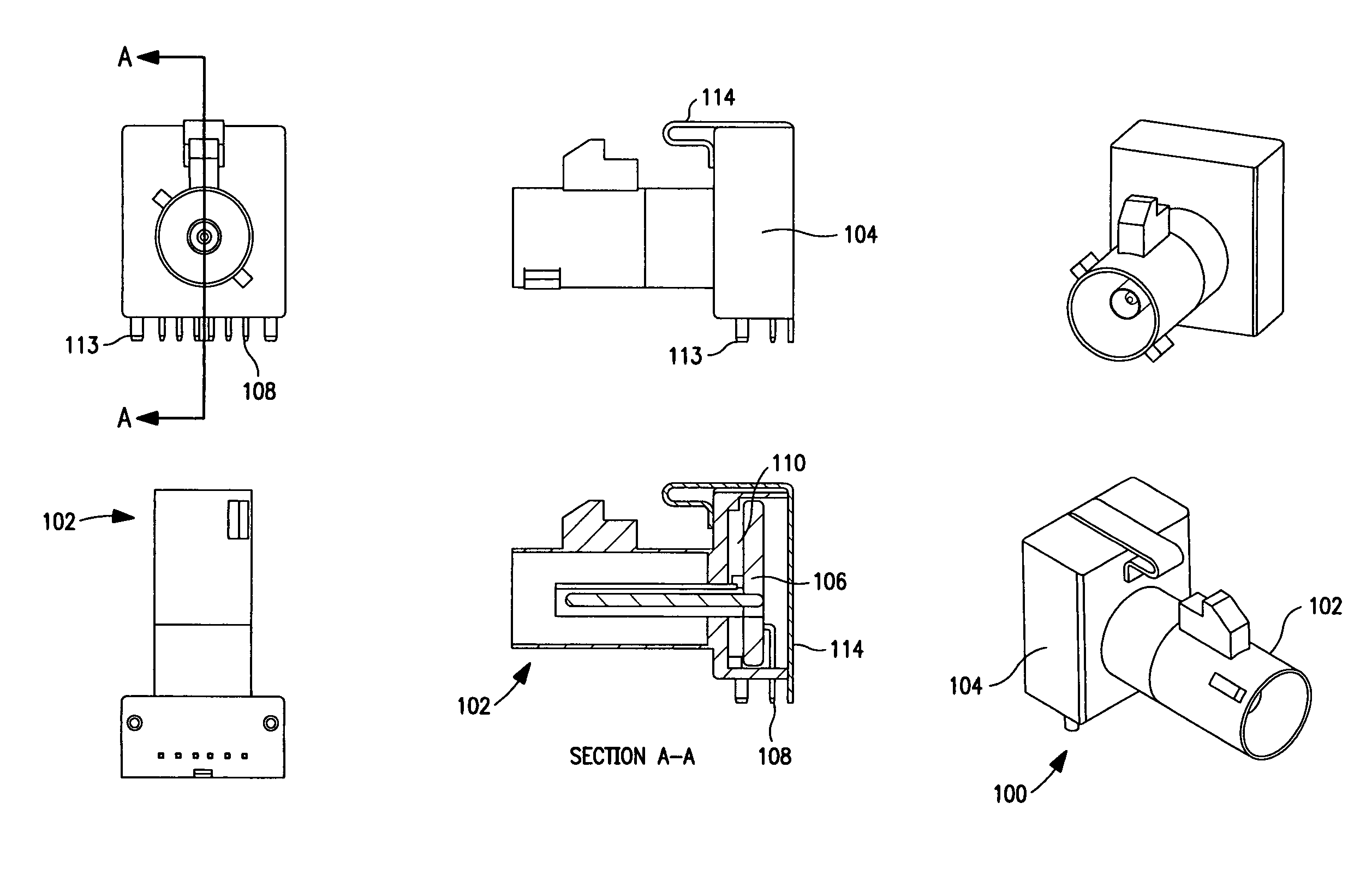
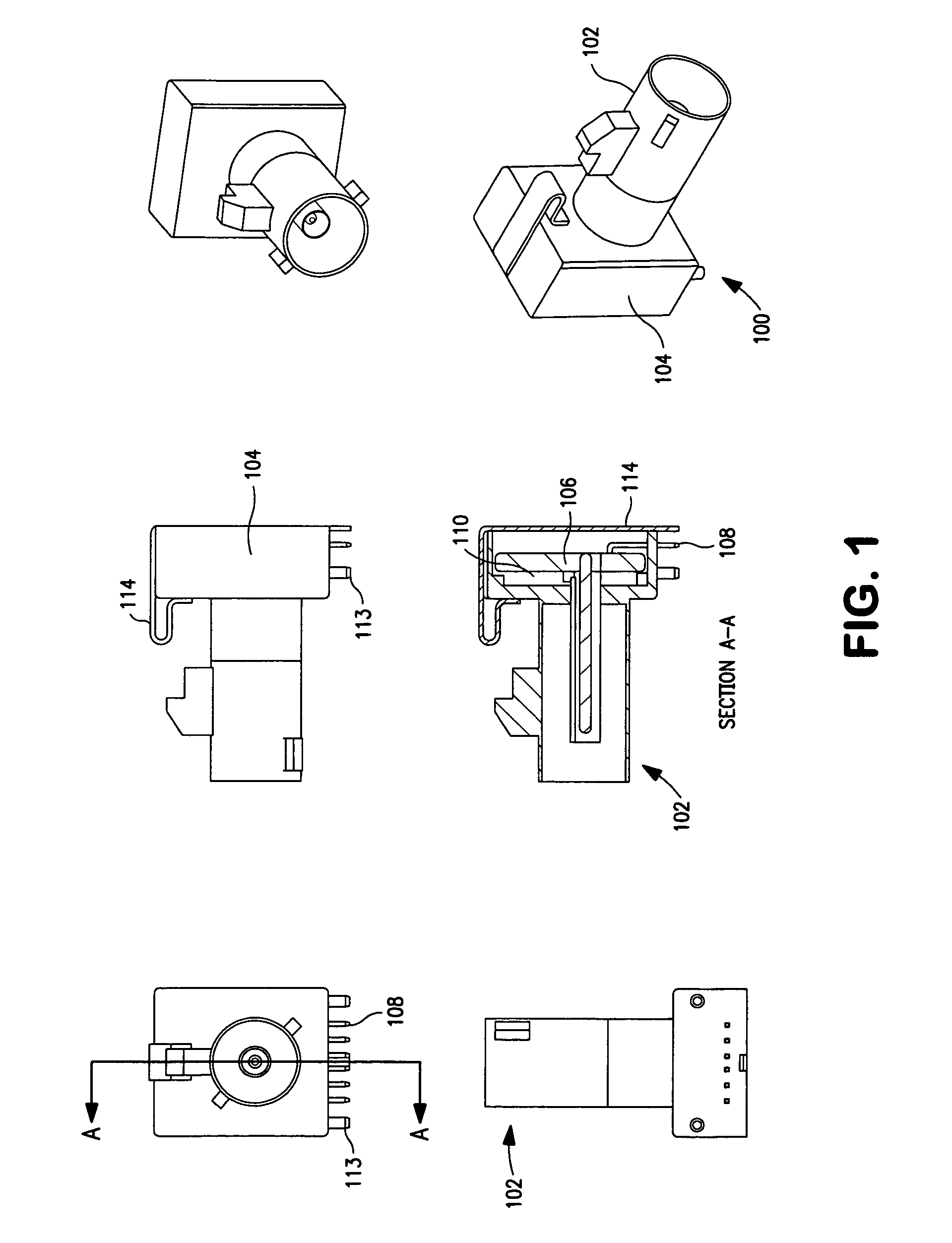
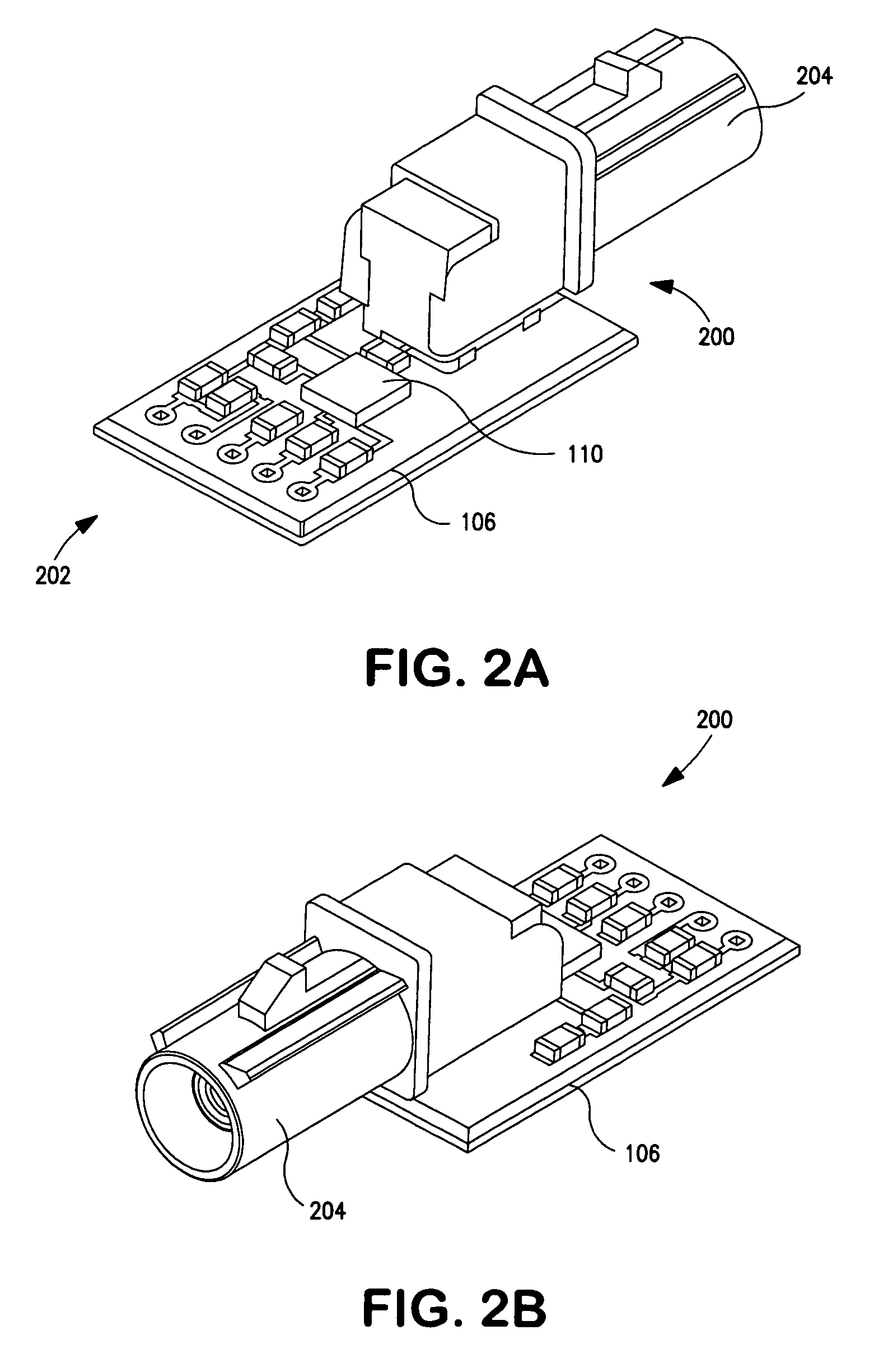
[0015]In a second embodiment, the connector is adapted for mating with a coaxial cable and adapted for providing a high-speed signal interface between said cable and an electronic device, and comprises: a coaxial cable connector; a connector housing comprising a noise shield and a substantially shielded volume formed therein; and an integrated circuit in signal communication with said connector and disposed substantially within said shielded volume, said integrated circuit adapted to provide at least one signal conditioning function. The shield is adapted to mitigate at least noise radiated from said integrated circuit and at least one other electronic component disposed within said shielded volume.
[0030]In a fourth aspect of the invention, a method of reducing the degree of modification required to an electronic device in order to accommodate a standardized signal interface is disclosed.
[0031]In a fifth aspect of the invention, a shielded connector adapted for mating with a coaxial cable is disclosed. In one embodiment, the connector is adapted for providing an IEEE Std. 1394-compliant interface between the cable and an electronic device, the connector comprising an integrated circuit disposed substantially within a shielded volume of the connector, the shielding being provided substantially by an external noise shield, the integrated circuit adapted to provide at least one signal conditioning function, the shield adapted to mitigate at least noise radiated from the integrated circuit and at least one other electronic component disposed within the shielded volume.
[0037]In a seventh aspect of the invention, a method of reducing the degree of modification required to an electronic device in order to accommodate a standardized signal interface is disclosed.
[0042]In one variant, the installing a coaxial cable comprises installing a cable that is both lower in cost and more mechanically rugged than the optical fiber.

Problems solved by technology

POF is not serviceable, and requires point-to-point routing.
Inline connectors severely affect the performance of POF in many applications such as automobiles due to alignment issues that are caused by vibration, temperature and mechanical alignment of the POF in the connector.
Minimum bend radii for POF is typically >25 mm, which is very difficult to package in automotive applications which often require smaller radii.
Moreover, automotive POF is limited in the maximal length of the fibers.
Such FOTs inherently produce EMI (noise), and are sensitive to temperatures that occur in automotive applications.
Additionally, the aforementioned POF is susceptible to installation and repair-induced damage, such as when the vehicle is manufactured, or is serviced and must have some of this POF removed for access or replacement of components.
They are also comparatively expensive due to their relatively complex construction and precision requirements.
The fiber optic solution is costly, and requires that the premises be wired with POF throughout to support the 1394 capability.
In addition to added cost, this often requires added care in the routing of the cable as with the aforementioned automotive applications (so as to avoid incidental nicks or other damage which can significantly affect fiber optic performance), and components at either end of the cable.
Alternatively, TSPs or “quads” (quad twisted shielded pair cables) may be able to provide sufficient EMI / RFI suppression and bandwidth, but are very costly and generally not part of the installed cabling base in premises.

Method used


Image

  • Low-cost connector apparatus and methods for use in high-speed data applications
  • Low-cost connector apparatus and methods for use in high-speed data applications
  • Low-cost connector apparatus and methods for use in high-speed data applications

Examples


Embodiment Construction

[0065]Reference is now made to the drawings wherein like numerals refer to like parts throughout.

[0066]As used herein, the terms “client device”, “peripheral device” and “end user device” include, but are not limited to, personal computers (PCs) and minicomputers, whether desktop, laptop, or otherwise, set-top boxes, personal digital assistants (PDAs) such as the “Palm®” or Blackberry families of devices, handheld computers, personal communicators, personal media devices (PMDs), J2ME equipped devices, cellular telephones or smartphones, or literally any other device capable of interchanging data with a network.

[0067]As used herein the term “coaxial cable” refers without limitation to any cable or interface having a substantially coaxial conductor or shield arrangement including for example RG-6 / U, RG-6 / UQ, RG-8 / U, RG-9 / U, RG-11 / U, RG-58 / U, RG-59 / U, RG-62 / U, RG-62A, RG-174 / U, RG-178 / U RG-179 / U, RG-213 / U, RG-214, RG-218, RG-223, and RG-316 / U. See, inter alia, Appendix I hereto—Exempla...


PUM


Abstract

Low-cost connector apparatus for passing electrical signals from one device over another via a cable. In one embodiment, the connector apparatus comprises a coaxial type connector that mates with a host device, such as via the motherboard thereof. In one variant, the connector further comprises a plurality of electrical components including an integrated circuit adapted to condition (e.g., equalize) the signals being transmitted over the cable. The connector (and hence internal electrical components) is shielded so as to mitigate the effects of EMI or RFI on the host device circuitry itself. In another variant, the signals comprise IEEE-Std. 1394 “FireWire” high speed data signals, and the use of the shielded connector in the signal pathway allows the use of lower cost cabling than would otherwise be required with a non-shielded (non-integrated) connector.

Description

PRIORITY[0001]This application claims priority to U.S. provisional patent application Ser. No. 61 / 009,450 filed Dec. 28, 2007 entitled “CONNECTOR APPARATUS AND METHODS”, which is incorporated herein by reference in its entirety.COPYRIGHT[0002]A portion of the disclosure of this patent document contains material that is subject to copyright protection. The copyright owner has no objection to the facsimile reproduction by anyone of the patent document or the patent disclosure, as it appears in the Patent and Trademark Office patent files or records, but otherwise reserves all copyright rights whatsoever.FIELD OF THE INVENTION[0003]The present invention relates generally to electrical connectors and signal transfer, and more particularly in one exemplary aspect to substantially compact and unified connector apparatus for transferring high-speed data signals (and optionally power), and methods of operating and manufacturing the same.DESCRIPTION OF RELATED ART[0004]In the case of automot...

Claims


Application Information

Patent Timeline
Patent Type & Authority Patents(United States)
IPC IPC(8): H04B3/00H01R13/6581H01R13/66H01R13/719H01R24/42H01R24/52
CPCH01R13/6581H01R13/6658H01R13/719H01R24/42H01R24/52
Inventor BUTTS, LAWRENCE DALEFUST, ROBERT E.SIMMEL, GEORGE MARC
Owner AUTOSPLICE SYST
Why Eureka
Try Eureka