
Routing method and system for a wireless network

a wireless network and routing method technology, applied in the field of routing methods and wireless networks, can solve problems such as too complicated data forwarding, and achieve the effect of reducing or extending the wireless deploymen

Active Publication Date: 2015-02-03
EXTREME NETWORKS INC
View PDF139 Cites 57 Cited by
  • Summary
  • Abstract
  • Description
  • Claims
  • Application Information

AI Technical Summary

Benefits of technology

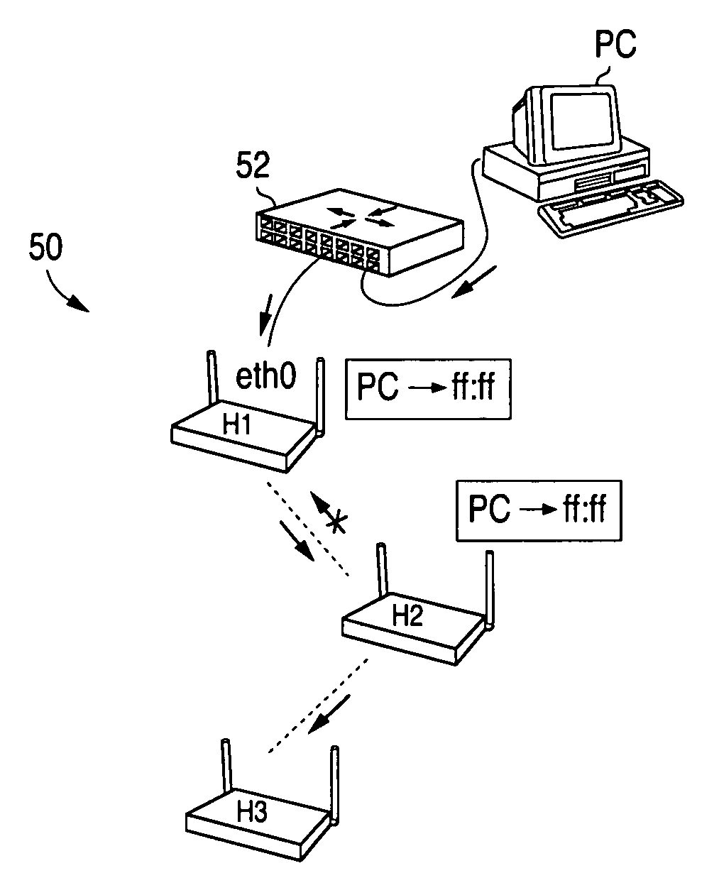
[0014]The present invention uses reverse-path-lookup rules to do broadcast loop prevention when forwarding broadcast and multicast traffic, to thereby provide an efficient way to handle wireless client mobility. When a data packet is received by a wireless node from a neighboring node, it detects if the data packet satisfies one of a plurality of predetermined conditions and rebroadcasts the data packet to neighboring wireless nodes if none of the conditions is satisfied. By contrast, both OLSR and AODV cache the per packet sequence number to eliminate the broadcast forwarding loop. This per packet state created in a device's data path introduces a significant complexity, thereby making data forwarding too complicated.
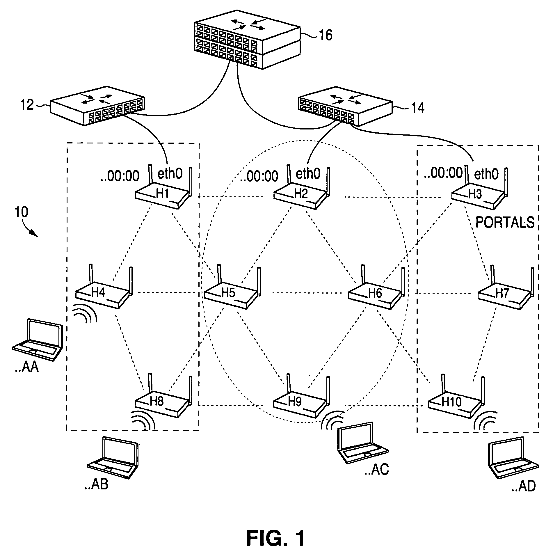
[0031]The present invention works with both wired and wireless backhaul links. It is designed to interoperate with existing Ethernet LAN switching technology. The user does not need to change any existing wired network topology to deploy a wireless access network according to the present invention, and a user always has the ability to easily extend or reduce the wireless deployment in the future.

Problems solved by technology

This per packet state created in a device's data path introduces a significant complexity, thereby making data forwarding too complicated.

Method used


Image

  • Routing method and system for a wireless network
  • Routing method and system for a wireless network
  • Routing method and system for a wireless network

Examples


Embodiment Construction

[0040]The present invention provides a method and system for synchronizing network link-state information, determining routing for each participating device, forwarding of data packets accordingly, and internetworking with existing Layer 2 switching networks.

[0041]According to the present invention, to synchronize link-state information for a particular node in a wireless network having a plurality of nodes, the node link-state must be broadcast to the whole network. Only a small subset of nodes are enabled to broadcast to the whole network. If a node belongs to this subset, the node is called a “portal” node. Preferably each portal node also is a backhaul link to an external wired LAN, e.g., an Ethernet link to the an Internet Service Provider (ISP). All other wireless nodes will have to unicast their link-state to one of the portal nodes, and then that portal node will aggregate and broadcast the nodes' link-states to the whole network. Eventually, each node within the network wil...


PUM


Abstract

A method and system for selecting a route in a wireless network for the transmission of a data packet between wireless nodes in said network using a modified link-state routing algorithm wherein only a limited number of broadcast messages are generated to synchronize the link-state database throughout the wireless network. A subset of nodes called portal nodes within the network are elected to do the broadcasting for the entire network. Each portal node broadcasts an announcement of its identity to all of the wireless nodes. Each wireless node responds to these broadcasts to select one of the portal nodes as its root portal node. It then identifies a unicast route back to its root portal node, and sends a link-state register message to this portal node. These link-state register messages received by each portal node are aggregated by them and are broadcast to each of the wireless nodes for storage. When a data packet is thereafter received by a wireless node from a neighboring node, it detects if the data packet satisfies one of a plurality of predetermined conditions and rebroadcasts the data packet to neighboring wireless nodes if none of the conditions is satisfied.

Description

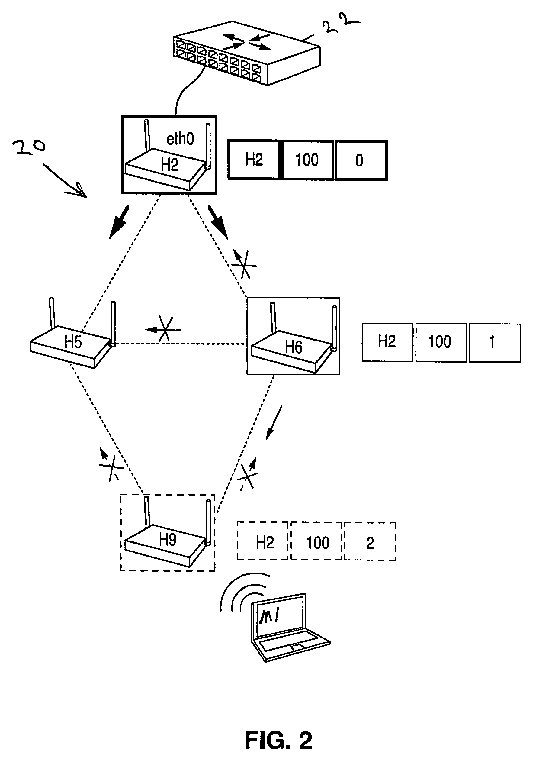
[0001]This application claims the benefit of U.S. Provisional Patent Application Ser. No. 60 / 926,590, filed Apr. 27, 2007, pursuant to 35 U.S.C. §119(e).BACKGROUND OF THE INVENTION[0002]The present invention relates to methods and systems for enabling data packets to be routed through a wireless network, where the network comprises a number of individual wireless transceivers configured to enable data packets to move or hop from one wireless transceiver or node to another until they reach a given destination. More particularly, the present invention includes a routing protocol that uses a modified link-state routing algorithm to make fast routing computations and reverse-path-lookup rules to prevent broadcast loops.[0003]A trend in distributed networks is the proliferation of wireless applications for voice, fax, paging, data, images, and video. The use of these wireless applications is expanding to true global coverage through the use of satellite networks and in-flight data commun...

Claims


Application Information

Patent Timeline
Patent Type & Authority Patents(United States)
IPC IPC(8): H04L12/28H04L45/02H04L45/122H04L45/18H04L45/24H04L45/243H04W4/06H04W40/02H04W40/24H04W40/30H04W40/36H04W84/00
CPCH04W40/24H04L45/18H04L45/00H04L45/20H04W4/06H04L45/02H04W40/02H04W40/36H04L45/22H04W84/005H04W40/30H04L41/0894H04L45/03H04L69/22H04L45/245H04L41/0893H04W40/246
Inventor KANG, YONGLIU, CHANGMING
Owner EXTREME NETWORKS INC
Learn More