
Silica glass crucible for pulling up silicon single crystal and method for manufacturing thereof

a technology of silicon single crystal and crucible, which is applied in the direction of crystal growth process, manufacturing tools, and protective fluids, etc., can solve the problems of easy damage to the polysilicon, easy formation of dents, and easy hotness of the crucible bottom, so as to prevent the generation of void defects and high quality

Active Publication Date: 2015-02-10
SUMCO CORP
View PDF18 Cites 0 Cited by
  • Summary
  • Abstract
  • Description
  • Claims
  • Application Information

AI Technical Summary

Benefits of technology

[0008]The present invention solves the problems described above and the object of the present invention is to provide a silica glass crucible for pulling up a silicon single crystal which can prevent the production of void defects caused by gas bubbles included within the silicon single crystal. In addition, the object of the present invention is to provide a manufacturing method of a silica glass crucible which can manufacture a high quality silicon single crystal without void defects caused by gas bubbles.
[0009]As a result of repeated keen research into the mechanism in which gas bubbles are generated within a crucible which should solve the above described problem, the inventors of the present invention discovered that the thickness of a synthetic silica layer at the crucible bottom participates significantly in the generation of gas bubbles and that it is possible to control the generation of gas bubbles when the synthetic silica layer at the crucible bottom is comparatively thin.
[0010]Presently, many of the silica glass crucibles which are used for pulling up a large diameter silicon single crystal are arranged with a synthetic silica layer on an inner layer. This is because synthetic silica has a lower level of impurities than natural silica and therefore the single crystal yield is considered to be high when growing the silicon single crystal over a long period of time. However, because synthetic silica has a low viscosity, places where fragments of the polysilicon come into contact are easy damaged and dents are easily formed by polysilicon chunks eating into the places where the synthetic silica layer is softened. This kind of phenomenon becomes more pronounced the thicker the synthetic silica layer and the possibility that the crucible inner layer will be deformed is high. Furthermore, the crucible bottom easily becomes very hot and SiO gas which is the cause of void defects is easily generated.

Problems solved by technology

However, because synthetic silica has a low viscosity, places where fragments of the polysilicon come into contact are easy damaged and dents are easily formed by polysilicon chunks eating into the places where the synthetic silica layer is softened.
Furthermore, the crucible bottom easily becomes very hot and SiO gas which is the cause of void defects is easily generated.

Method used


Image

  • Silica glass crucible for pulling up silicon single crystal and method for manufacturing thereof
  • Silica glass crucible for pulling up silicon single crystal and method for manufacturing thereof
  • Silica glass crucible for pulling up silicon single crystal and method for manufacturing thereof

Examples


example 1

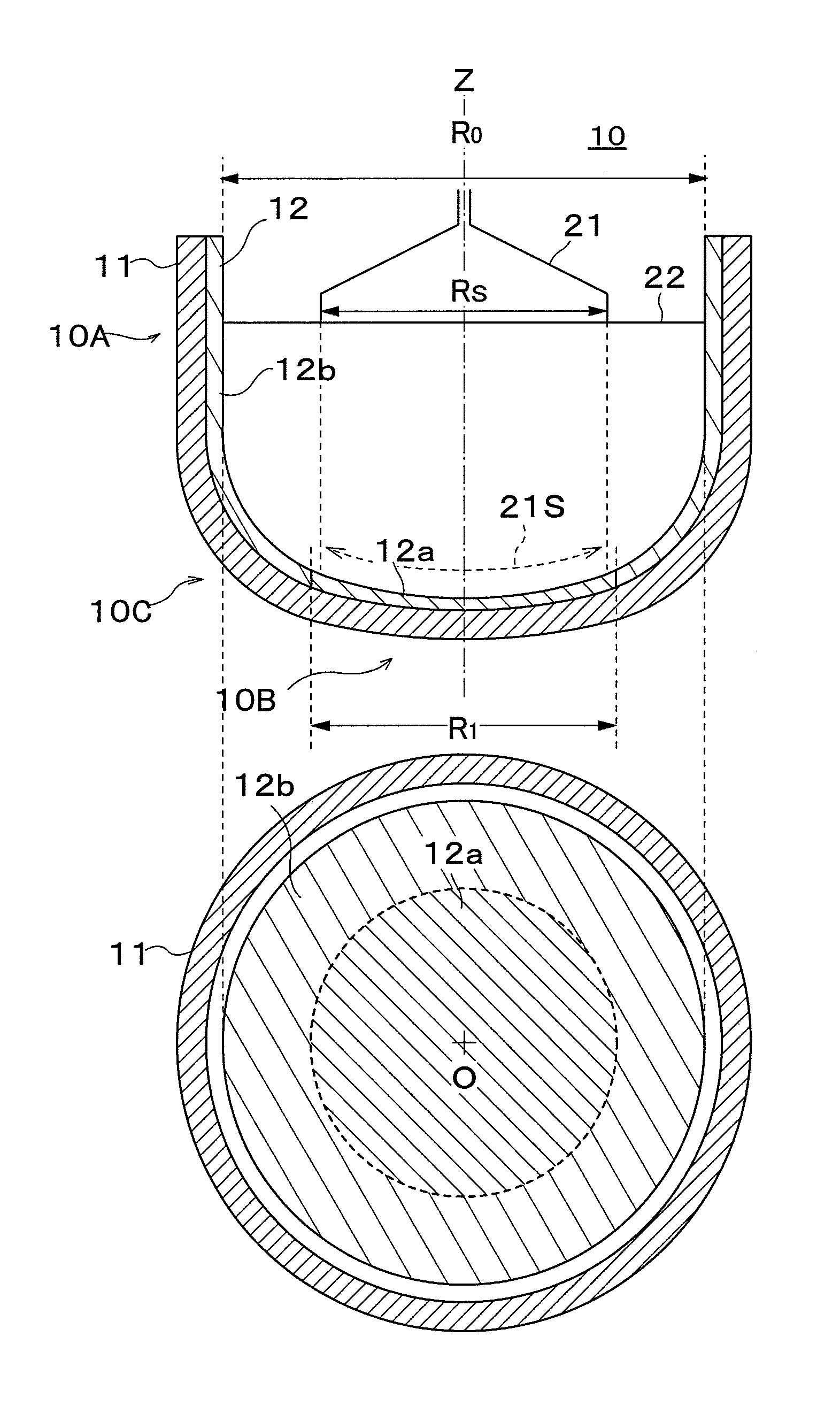
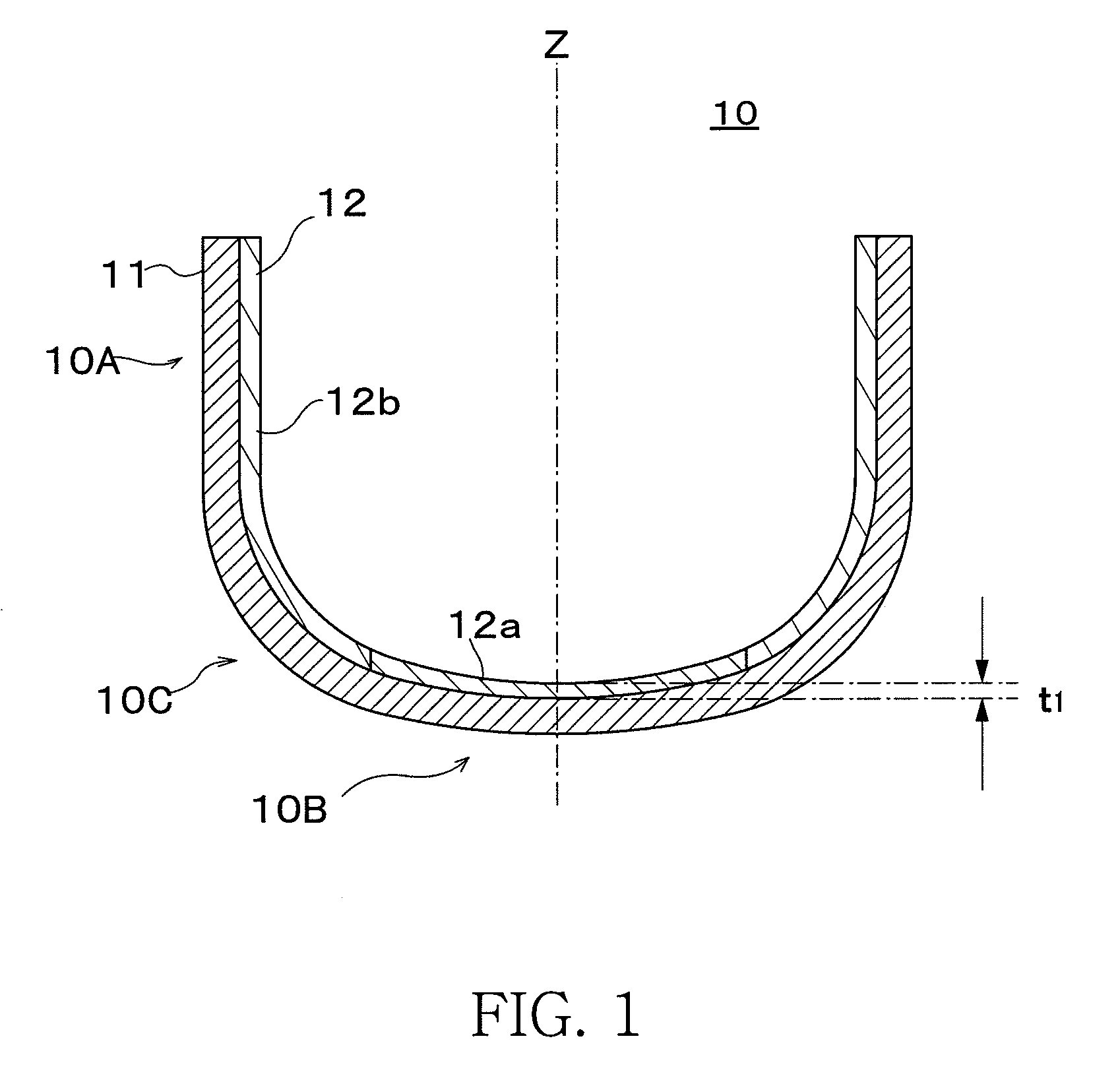
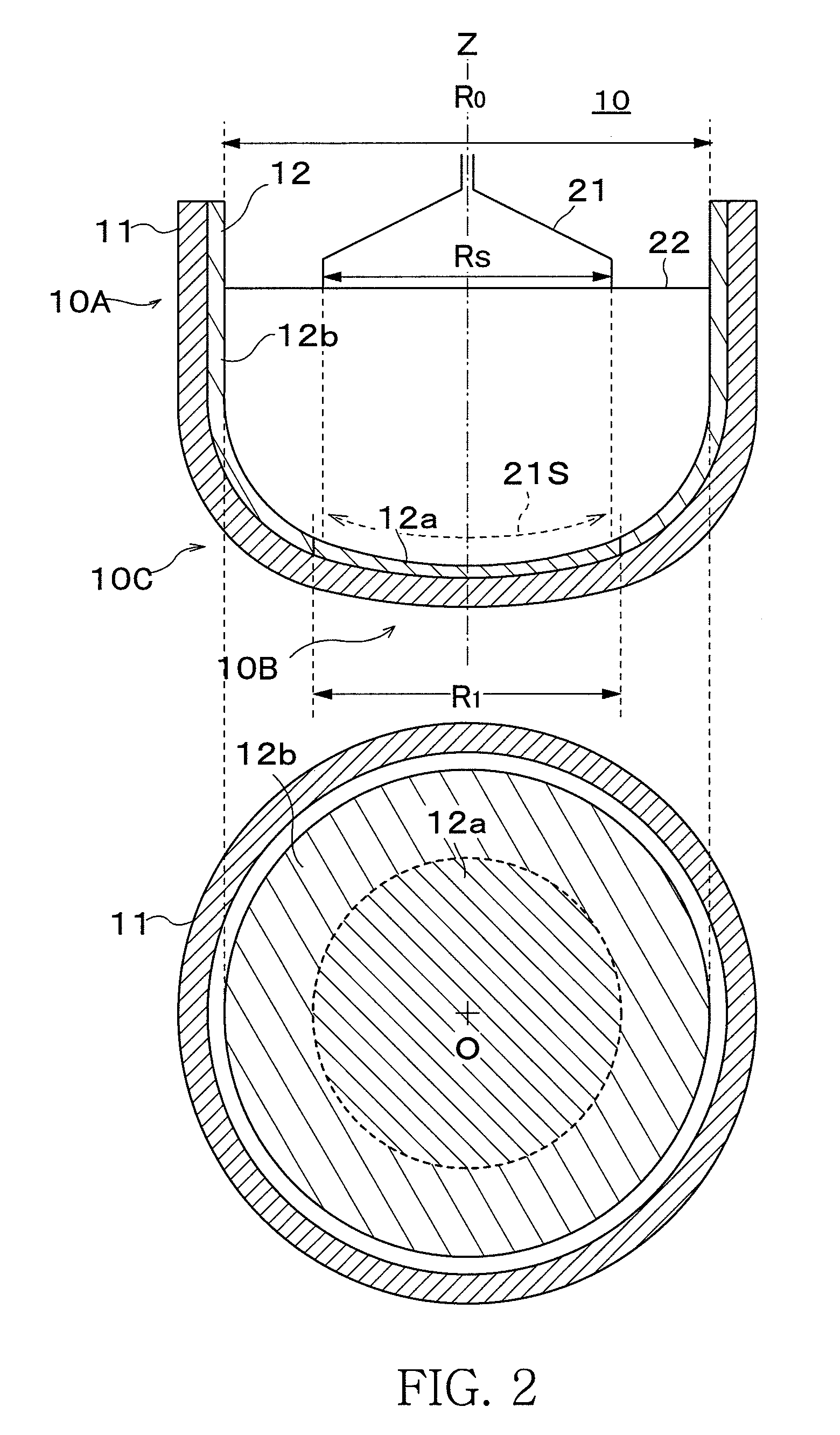
[0053]A sample of a silica glass crucible having the structure shown in FIG. 1 was prepared. The crucible sample had a diameter of 32 inches (diameter R0=800 mm), crucible height of 500 mm, and sidewall section thickness of 17 mm, corner section thickness of 25 mm and bottom section thickness of 14 mm from the inner surface to the exterior surface of the crucible. In addition, the diameter of the first synthetic silica glass layer is 400 mm, thickness was 1.0-1.3 mm (1.0 mm is the thinnest section in the center of the crucible bottom section, 1.3 mm is the thickest section in a periphery position R / 2 from the bottom section center, the same is true below), the average OH group concentration (below referred to simply as OH group concentration) of a range up to a depth of 2 mm from the inner surface of the synthetic silica glass layer was 100 ppm, and the total impurity concentration of Na, K and Li in the natural silica glass layer was 0.5 ppm and the impurity concentration of Al in ...

example 2

[0058]Other than a thickness of the first synthetic silica glass layer being 0.8-1.1 mm and the OH group concentration being 70 ppm, a crucible sample having the same structure as in example 1 was prepared, the silicon single crystal was pulled up under the same conditions as example 1, and the pinhole generation rate of the silicon single crystal ingot was measured. As a result, as shown in Chart 1, the first synthetic silica glass layer was thinner than in example 1, and the pinhole generation rate of example 2 which had a lower OH group concentration was 0.04% which was even lower than the pinhole generation rate of example 1. In addition, the single crystal yield was 1.

example 3

[0059]Other than the total impurity concentration of Na, K and Li of the natural silica glass layer being 0.1%, a crucible sample having the same structure as in example 2 was prepared, the silicon single crystal was pulled up under the same conditions as example 1, and the pinhole generation rate of the silicon single crystal ingot was measured. As a result, as shown in Chart 1, the pinhole generation rate of example 3 which had a lower total impurity concentration of Na, K and Li than example 2 was 0.02%, which was the lowest pinhole generation rate of all the examples. In addition, the single crystal yield was 1.


PUM

PropertyMeasurementUnit
thicknessaaaaaaaaaa
thicknessaaaaaaaaaa
thicknessaaaaaaaaaa

Abstract

A silica glass crucible for pulling up a silicon single crystal including an outer layer formed from a natural silica glass layer, and an inner layer formed from a synthetic silica glass layer, wherein the synthetic silica glass layer includes a first synthetic silica glass layer formed in a region within a certain range from the center of a crucible bottom section, and a second synthetic silica glass layer formed in a region which excludes the formation region of the first synthetic silica glass layer, and wherein the first synthetic silica glass layer has a thickness of 0.5 mm or more and 1.5 mm or less and a concentration of an OH group included in the first synthetic silica glass layer being 100 ppm or less.

Description

TECHNICAL FIELD[0001]The present invention is related to a silica glass crucible used for pulling up a silicon single crystal and a method for manufacturing the silica glass crucible. In particular, the present invention is related to a layer structure of the silica glass crucible.BACKGROUND OF THE INVENTION[0002]A silica glass crucible is used in the manufacture of a silicon single crystal. In a Czochralski (CZ) method, polysilicon is charged into a silica glass crucible, heated and melted and a seed crystal is immersed in this silicon melt, and while mutually rotating the crucible and the seed crystal, the seed crystal is slowly pulled up and a silicon single crystal is grown. In order to manufacture a high purity silicon single crystal for use in semiconductor devices, it is necessary that the silicon single crystal not be polluted by an elution of impurities which are included within the silica glass crucible and in addition, the silica glass crucible requires sufficient heat re...

Claims


Application Information

Patent Timeline
Patent Type & Authority Patents(United States)
IPC IPC(8): C30B15/10C03B19/09
CPCC03B19/095C30B15/10Y10S117/90Y10T117/10Y10T117/1032Y10T117/1052Y02P40/57C03B19/09
Inventor HARADA, KAZUHIROMORIKAWA, MASAKIKUDO, SATOSHI
Owner SUMCO CORP
Learn More