Considering compatibility of adjacent boundary regions for standard cells placement and routing

a technology of compatibility and boundary region, applied in the field of integrated circuits, can solve the problems of reducing the efficiency of the circuit layout, limiting the flexibility of cell placement and connection routing, and unable to place cells next to each other in the integrated circuit layout, so as to reduce the area of the eventual integrated circuit layout, improve the routing of connections, and improve the flexibility

Active Publication Date: 2015-02-17
ARM LTD
View PDF18 Cites 28 Cited by
  • Summary
  • Abstract
  • Description
  • Claims
  • Application Information

AI Technical Summary

Benefits of technology

[0009]The method determines a placement of standard cells selected from the cell library while permitting one or more boundary conflicts in which incompatible regions are placed adjacent to each other in adjacent standard cells of the placement. This is in contrast to known systems which would not allow such placement with boundary conflicts. A mapping step is provided later in the layout generation method in which, for at least one of the boundary conflicts, at least one of the incompatible boundary regions in the placement is mapped to an alternative boundary region to resolve the boundary conflict. This technique provides several advantages. By providing the mapping step subsequent to placement and routing, the placement and routing steps become less complex as they do not need to consider compatibility of boundary regions of adjacent cells. Also, this technique allows for greater flexibility in choosing which cells are placed in the cell placement, which may permit better routing of connections between the standard cells for example. Also, by placing the standard cells while permitting boundary conflicts, but later mapping incompatible boundary regions to alternative boundary regions to resolve the conflicts, it is possible to place the standard cells without using a filler region between incompatible boundary regions, thus reducing the area of the eventual integrated circuit layout.
[0010]The step of determining the placement of standard cells may include placing a reflected cell in the placement, the reflected cell comprising a reflected version of a selected standard cell from the standard cell library. Providing the ability to reflect cells from the library when placing them in the placement is useful because this can allow connections to be routed to the cell more efficiently, freeing space for other routings. However, if the cell to be reflected has different boundary regions at different edges of the cell, then reflecting the cell may introduce boundary conflicts which would not have been present if the cell had not been reflected since the reflection may cause the boundary regions to be exchanged in position. Hence, in known integrated circuit layout design, it has been difficult to introduce reflected cells without also requiring filler regions to be added to resolve boundary conflicts. In contrast, the present technique can permit such boundary conflicts caused by reflected cells in the placement, and then subsequently map incompatible boundary regions to alternative boundary regions to resolve the conflict once the placement and routing has been determined. Hence, the benefits of the reflected cell placement can still be achieved without complicated modification of the cell placement step or routing step and without filler regions increasing the circuit area. The reflection of the cell may be about any axis. For example, the reflection may be about an axis which divides the cell in two horizontally, vertically or diagonally.
[0015]Hence, for a given functional component, it can be useful for the cell library to contain characterising information defining two different versions of a standard cell for the same component. A first version has a first boundary region at one edge, a second boundary region at an opposite edge and a given functional component between the two edges. The alternative version has the functional component reflected compared to the first version but the boundary regions in the same place as the first version. The target standard cell discussed above may correspond to a reflected form of the first version and so the library would not need to contain further characterising data defining this reflected form as the first version can implicitly identify the reflected target standard cell. Hence, boundary conflicts introduced by reflecting the first version of the cell to produce the target standard cell for the placement can be resolved by replacing the target standard cell with the second version of the cell at the mapping stage.
[0018]The mapping step may be performed at various stages of the method of generating the integrated circuit layout. In one example, the mapping step may be performed at a “streamout” step for outputting the integrated circuit layout for design rule verification or manufacturing rule verification. Design or manufacturing rule verification may comprise various checks for ensuring that the generated integrated circuit layout will function correctly when manufactured. It is advantageous to perform the mapping step at the streamout stage, because at this point less data is required to characterise the placed cells than at the placement or routing stage. If the mapping step using alternative versions of standard cells as discussed above had been performed at the placement or routing step, then this would require each version of the cell to be modelled fully for placement / routing, which would increase the volume of data and complexity of the standard cell library. However, at the streamout step, the alternative versions of cells can be defined using less data, making the cell library's implementation more efficient.
[0029]On the other hand, in other examples only the first standard cell may be available for placement and routing (whether in non-reflected or reflected form), and the second standard cell may then replace the reflected version of the first standard cell at a subsequent mapping step for resolving boundary conflicts. In this case, the standard cell library may comprise a control information for controlling placement and connection routing for the first standard cell only, but not the second standard cell. This approach may be more efficient as the amount of characterising data for defining the second standard cell can be reduced by inserting it at a later stage of the layout generation process rather than requiring the model of the cell to be fully duplicated at the placement / routing stage.

Problems solved by technology

Some cells may have boundary regions which are incompatible with each other, so that such cells cannot be placed next to each other in the integrated circuit layout.
However, this limits flexibility in cell placement and routing of connection to the cells, which can reduce the efficiency of the circuit layout.
However, the filler regions increase the area of the integrated circuit layout, which is undesirable.

Method used


Image

  • Considering compatibility of adjacent boundary regions for standard cells placement and routing
  • Considering compatibility of adjacent boundary regions for standard cells placement and routing
  • Considering compatibility of adjacent boundary regions for standard cells placement and routing

Examples


Embodiment Construction

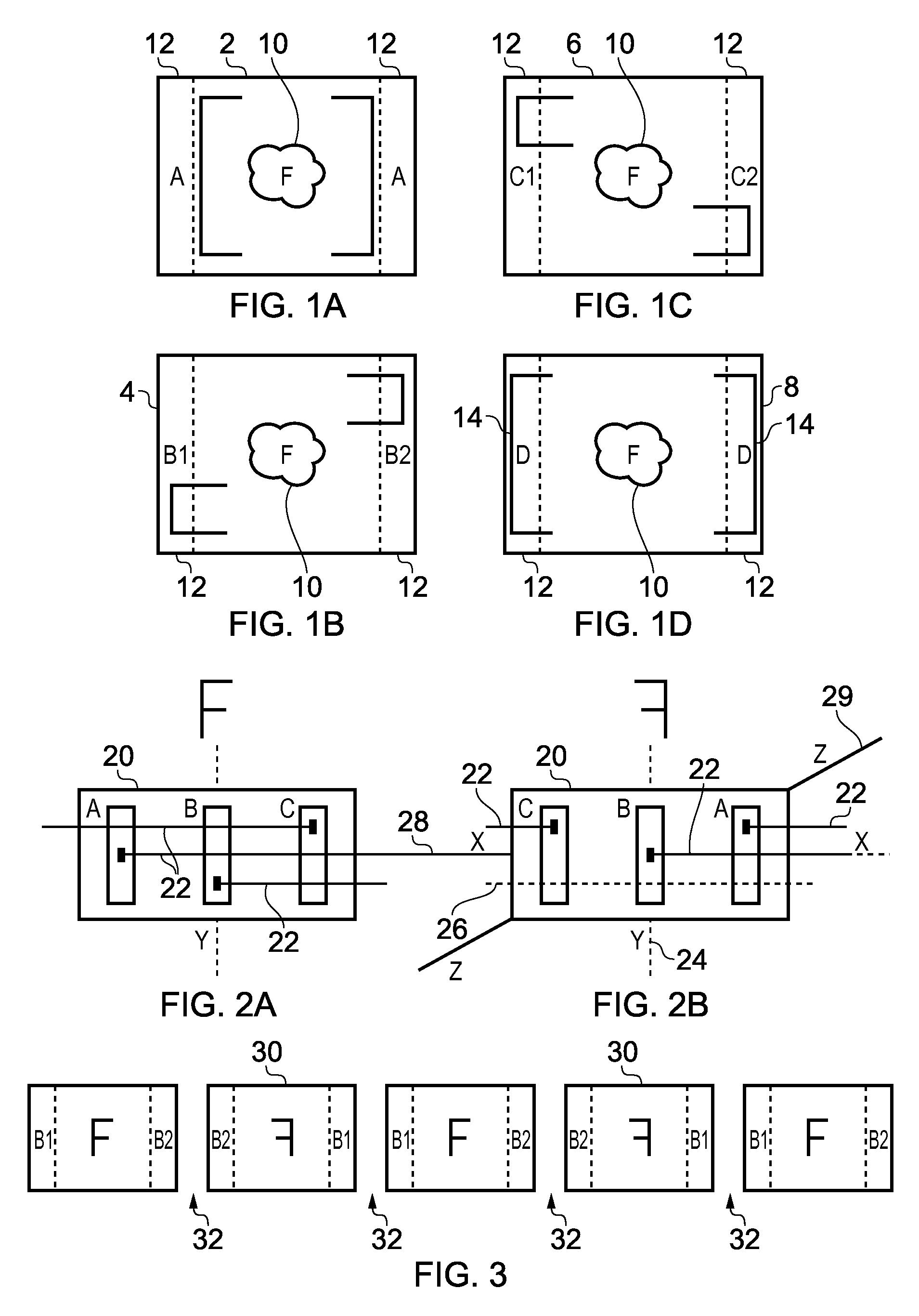
[0041]FIGS. 1A to 1D illustrate four examples of standard cells 2, 4, 6, 8 for potential inclusion in an integrated circuit layout. Each standard cell comprises functional circuitry 10 which may comprise any component of an integrated circuit. For example, the functional circuitry 10 may be a logic gate such as an AND gate or OR gate, an adder, or a multiplier. The letter F will be used in the drawings to denote the functional component. Each standard cell includes boundary regions 12 at the edges of the standard cell. While FIGS. 1A to 1D shows the boundary regions 12 at the left and right edges of the cell, in other examples, there may be boundary regions at the top and bottom edges instead of, or in addition to, the left and right edges.

[0042]Integrated circuit design rules or other constraints may cause boundary regions 12 of different types to be incompatible with each other so that they cannot be placed abutting each other in the integrated circuit layout. For example, there m...


PUM


Abstract

A method of generating an integrated circuit layout comprises a step of determining a placement of standard cells selected from a standard cell library while permitting boundary conflicts in which incompatible boundary regions of standard cells are placed next to each other. After determining routing connections between the standard cells, the integrated circuit layout is generated. The generation of the integrated circuit layout includes a mapping step of mapping at least one incompatible boundary region to an alternative boundary region to resolve at least one boundary conflict.

Description

TECHNICAL FIELD[0001]The present invention relates to the field of integrated circuits. More particularly, the invention relates to a method of generating an integrated circuit layout.BACKGROUND[0002]Automated tools may be provided for generating an integrated circuit layout. A standard cell library defines different types of standard cells which can be selected for inclusion in the integrated circuit layout. The system designer can provide the automated design system with a functional definition of the circuit layout to be generated, and the automated design system can then generate an integrated circuit layout by selecting standard cells from the library which satisfy the required functional definition.[0003]It is known to provide some standard cells which have boundary regions which have limited compatibility with boundary regions of adjacent cells. Some cells may have boundary regions which are incompatible with each other, so that such cells cannot be placed next to each other ...

Claims


Application Information

Patent Timeline
Patent Type & Authority Patents(United States)
IPC IPC(8): G06F17/50
CPCG06F17/5072G06F17/5077G06F30/394G06F30/392G06F30/398
Inventor FREDERICK, JR., MARLIN WAYNEPELLOIE, JEAN-LUC
Owner ARM LTD
Why Eureka
Try Eureka