System and method for extending a lubricant discard interval

a technology of lubricant and interval, which is applied in the direction of instruments, mechanical equipment, structural/machine measurement, etc., can solve the problems of reducing the power output of the engine, wear on the moving parts, so as to minimize downtime, optimize overall cost, and cost-effective

Active Publication Date: 2015-02-24
AFTON CHEMICAL
View PDF49 Cites 11 Cited by
  • Summary
  • Abstract
  • Description
  • Claims
  • Application Information

AI Technical Summary

Benefits of technology

[0003]Engines for motors) are designed to convert one form of energy (such as, for example, fuel combustion, electricity, nuclear reactions, and the like) to mechanical energy, such as, for example, mechanical motion. For instance, combustion engines convert fuel combustion energy to motion energy. These engines typically include one or more combustion chambers that contain and confine the combustion of a fuel (e.g., a fossil fuel), allowing the resultant high temperature and high pressure gases to expand and drive mechanical components such as, for example, pistons, turbine blades, or the like.
[0005]Most of the moving parts in the engine are made of metal. During operation, metal to metal contact of the moving parts causes wear on the moving parts. To minimize wear of the moving parts, and, therefore, to maximize engine durability and longevity, a lubricant (e.g., an engine oil) is used to lubricate the moving parts in the engine. The lubricant may also function to clean, inhibit corrosion, improve sealing, and cool the engine by carrying heat away from the moving parts. The lubricant reduces friction by, for example, creating a separating film between surfaces of adjacent moving parts to minimize direct contact between the surfaces, decreasing heat caused by the friction and reducing wear.
[0012]Although it would seem ideal to analyze the condition of used oil from each piece of equipment and only change it when the analysis indicates it is close to the end of its useful life, there are other costs to consider in determining the most cost effective time to change oil. In their use, engines contribute to revenue production making it costly to take them out of service. As a consequence many maintenance tasks for equipment are preplanned and grouped together enabling these tasks to be performed during a planned shutdown of the equipment, or when many of the tasks can be performed simultaneously to minimize downtime. Equipment operators usually schedule maintenance to optimize overall cost. This means that to maximize production, individual maintenance tasks may be performed before they are actually needed.

Problems solved by technology

The various moving parts of the engine cause friction, which results in the wear of the moving parts and diminished power output of the engine.
During operation, metal to metal contact of the moving parts causes wear on the moving parts.
During operation of the engine, the lubricants undergo both thermal and mechanical degradation, and contamination which impairs their function.
Eventually the loss of performance may become significant enough to necessitate removal of the used lubricant and replacement with a fresh lubricant.
However, this drain interval may be too long for some engines, such as, e.g., engines that are operated under severe conditions, or engines that are experiencing performance issues, or new engines that have just been placed into service and are susceptible to break-in wear.
Also, new engines may require more frequent oil changes than older engines.
Again, the established oil drain intervals may be too long for some engines, while shorter than necessary for others.
Thus, fixed time / distance lubricant discard (or drain) intervals may result in the continued use of spent engine lubricant where an engine is operated under severe conditions or where the engine is not operating properly, which may result in poor fuel efficiency, costly maintenance, premature engine failure, and the like.
The fixed time / distance lubricant discard intervals may also result in the premature, and therefore, inefficient discarding of engine lubricant that remains unspent at the discard interval, thereby increasing the amount of waste byproduct to be disposed of, as well as the costs associated with the replacement of the engine lubricant (including, e.g., the cost of the lubricant, the cost of labor to replace the lubricant, disposal costs, engine down time costs, and the like).
Although it would seem ideal to analyze the condition of used oil from each piece of equipment and only change it when the analysis indicates it is close to the end of its useful life, there are other costs to consider in determining the most cost effective time to change oil.
In their use, engines contribute to revenue production making it costly to take them out of service.
Because it is often difficult to predict how much useful life remains in a used oil, oil change intervals are frequently standardized across like pieces of equipment in a business unit.
Some locomotives, particularly some GE FDL units under some operating conditions, cannot safely go for 276 days without an oil Change.
Thus, an unfulfilled need exists for a system and method to test used oil and predict at, for example, 150 days of service, based on the used oil analysis, which units should be changed at, e.g., 184 days, which units can safely continue to, e.g., 276 days without an oil change.
Volatile content losses may result in a lubricant viscosity increase due to thickening of the lubricant in the engine; (4) megawatt hours produced, wherein units that produce comparatively high levels of power may increase the “aging” rate of the lubricant in the crankcase, while production of low levels of power may decrease the “aging” rate of the lubricant; (5) total miles of the unit or engine between oil changes, wherein units having, higher or lower cumulative miles between oil changes may affect the “aging” rate of the lubricant in the engine; and (6) the age of the engine or unit, wherein engines or units that are relatively new may exhibit a higher metal content in the lubricant due to mating parts wearing or “breaking in” during the early life of the engine or unit.

Method used


Image

  • System and method for extending a lubricant discard interval
  • System and method for extending a lubricant discard interval
  • System and method for extending a lubricant discard interval

Examples


example 1

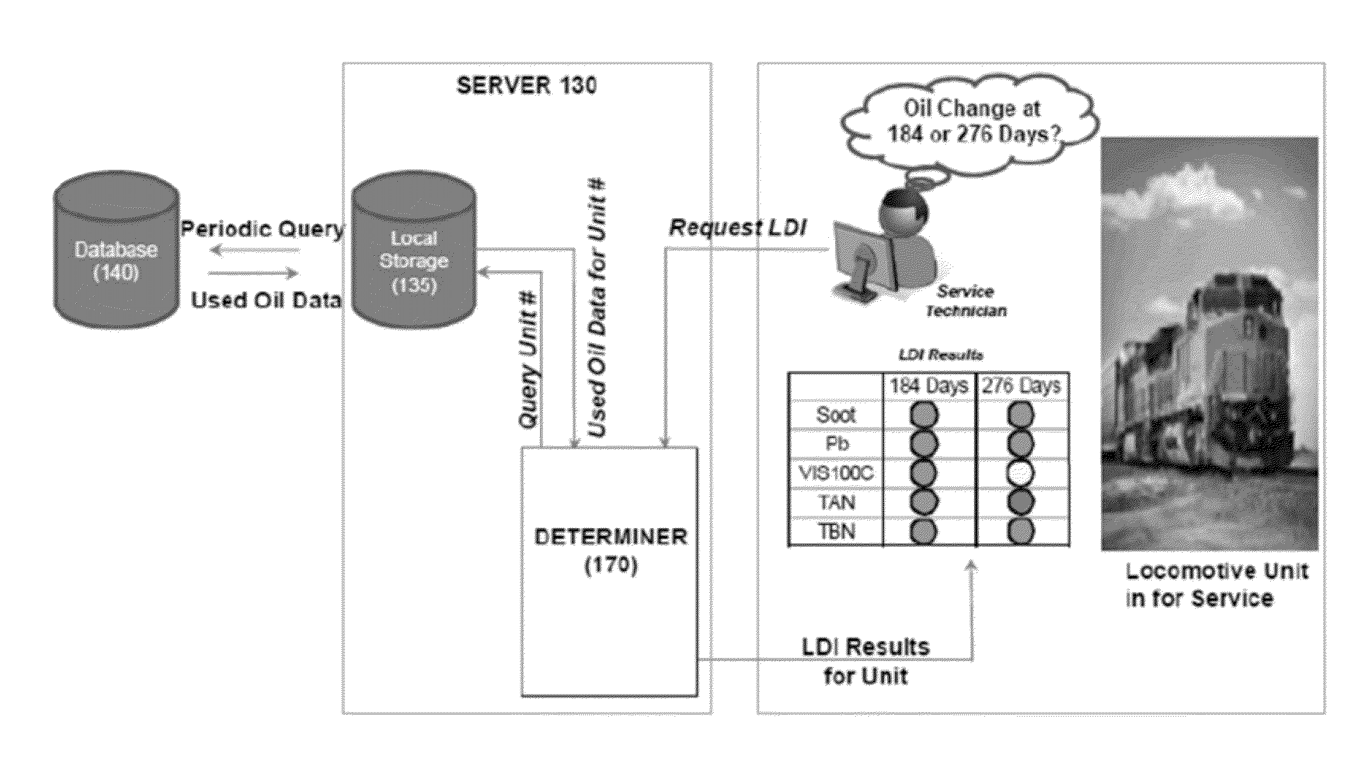
[0115]A locomotive engine is subject to maintenance every 92 days. A sample analysis at 184 indicates that that the oil has 61 days of useful life remaining. The system 100 is used to determine that the useful life can be increased to 92 days by removing 10% of the used oil and replacing with fresh oil. A maintenance manager obtains the output from the system and may then determine whether it is more advantageous to change the oil on that unit at 184 days or draining off 10% of the oil (and adding 10% fresh oil to the unit) and continuing on to 276 days of service before changing the oil.

example 2

[0116]In the following example a partial least squares analysis of data was used to determine when an analysis parameter value would be expected to exceed a threshold value. In the examples, t+X days are arbitrarily selected to illustrate how the analysis is conducted using the claimed system and methods. In the following tables, the values are of each parameter are determined by t+120 days by interpolating between existing data points for each of the measured parameters in a historical record for an engine. For example, Table 1 shows the interpolated values for iron for a particular engine a t+120 days, where t is the estimated oil age in days. Because there is some lag time between when a sample is obtained and the analysis of the sample is determined, the samples are not collected on the last day of a service interval. In other words, the analysis must be received before a selected service interval so that a decision can be made by the time the service interval date arrives. An e...

example 3

[0120]The foregoing analysis can also be done for non-linear data such as viscosity. Table 2 is a table of data for viscosity at 100° C. at t+30 days and t+120 days.

[0121]

TABLE 2

[0122]FIG. 18 is a scatter plot of observed versus predicted value of viscosity at 100° C. at t+120 days using a partial least squares model with a 3 latent variable model. FIG. 19 is a graphical representation of the amount of variation explained for a 3 latent variable model using the partial least squares model for predicting the viscosity at 100° C. at t+120 days for the data. FIG. 20 is a partial least squares model coefficient chart summary of the three latent variable model depicted in FIG. 19 showing the relative importance / effects of various parameters used for predicting the viscosity at 100° C. at r+120 days. FIGS. 21 and 22 are scatter plots of the multivariate data that was analyzed to predict the interpolated iron content and soot content at t+30 and t+120 days in the oil. The matrix plots also...


PUM


Abstract

A system, a method and a computer program to predict a portion of used lubricant in an engine that is to be drained and replaced by fresh lubricant based on an analysis parameter value that is measured in a sample of used engine lubricant from the engine. The system includes a first input that receives the analysis parameter value from the used lubricant and stores the analysis parameter value in a memory of a processor. A second input receives an analysis parameter threshold value for the used lubricant at the end of a service interval and stores the analysis parameter threshold value in a memory of the processor. A determiner predicts a future analysis parameter value of the used lubricant at the end of the service interval based on the analysis parameter value, and the analysis parameter threshold value.

Description

RELATED APPLICATION[0001]This application is a continuation-in-part of application Ser. No. 13 / 439,332, filed Apr. 4, 2012, now pending which is a continuation-in-part of application Ser. No. 13 / 363,433, filed Feb. 1, 2012, now pending.FIELD OF THE DISCLOSURE[0002]The present disclosure relates to a system, a method, and a computer program for determining usability of lubricants and when to replace all or part of the lubricants in, for example, an engine, a power transmission device, a turbine, a generator, a motor, or the like.BACKGROUND AND SUMMARY OF THE DISCLOSURE[0003]Engines for motors) are designed to convert one form of energy (such as, for example, fuel combustion, electricity, nuclear reactions, and the like) to mechanical energy, such as, for example, mechanical motion. For instance, combustion engines convert fuel combustion energy to motion energy. These engines typically include one or more combustion chambers that contain and confine the combustion of a fuel (e.g., a ...

Claims


Application Information

Patent Timeline
Patent Type & Authority Patents(United States)
IPC IPC(8): F01M11/10
CPCF01M11/10F01M2011/14F01M2011/1466F01M2011/1486F01M2011/1426F01M2011/1446F01M11/04G01N33/2858G01N33/2888
Inventor DVORAK, TODD M.DITTMEIER, ROBERT T.SZEMENYEI, DEWEY P.
Owner AFTON CHEMICAL
Why Eureka
Try Eureka