Secondary air injection system and method

a technology of secondary air injection and air injection system, which is applied in the direction of engines, machines/engines, mechanical equipment, etc., can solve the problem of reducing the energy provided by exhaust pressure pulses

Inactive Publication Date: 2015-03-03
GM GLOBAL TECH OPERATIONS LLC
View PDF56 Cites 4 Cited by
  • Summary
  • Abstract
  • Description
  • Claims
  • Application Information

AI Technical Summary

Problems solved by technology

However, secondary air injection systems may allow cross talk or degradation between cylinder groups by allowing communication between the exhaust flow of cylinder groups, thereby reducing energy provided by exhaust pressure pulses.

Method used


Image

  • Secondary air injection system and method
  • Secondary air injection system and method
  • Secondary air injection system and method

Examples


Embodiment Construction

[0011]The following description is merely exemplary in nature and is not intended to limit the present disclosure, its application or uses. It should be understood that throughout the drawings, corresponding reference numerals indicate like or corresponding parts and features.

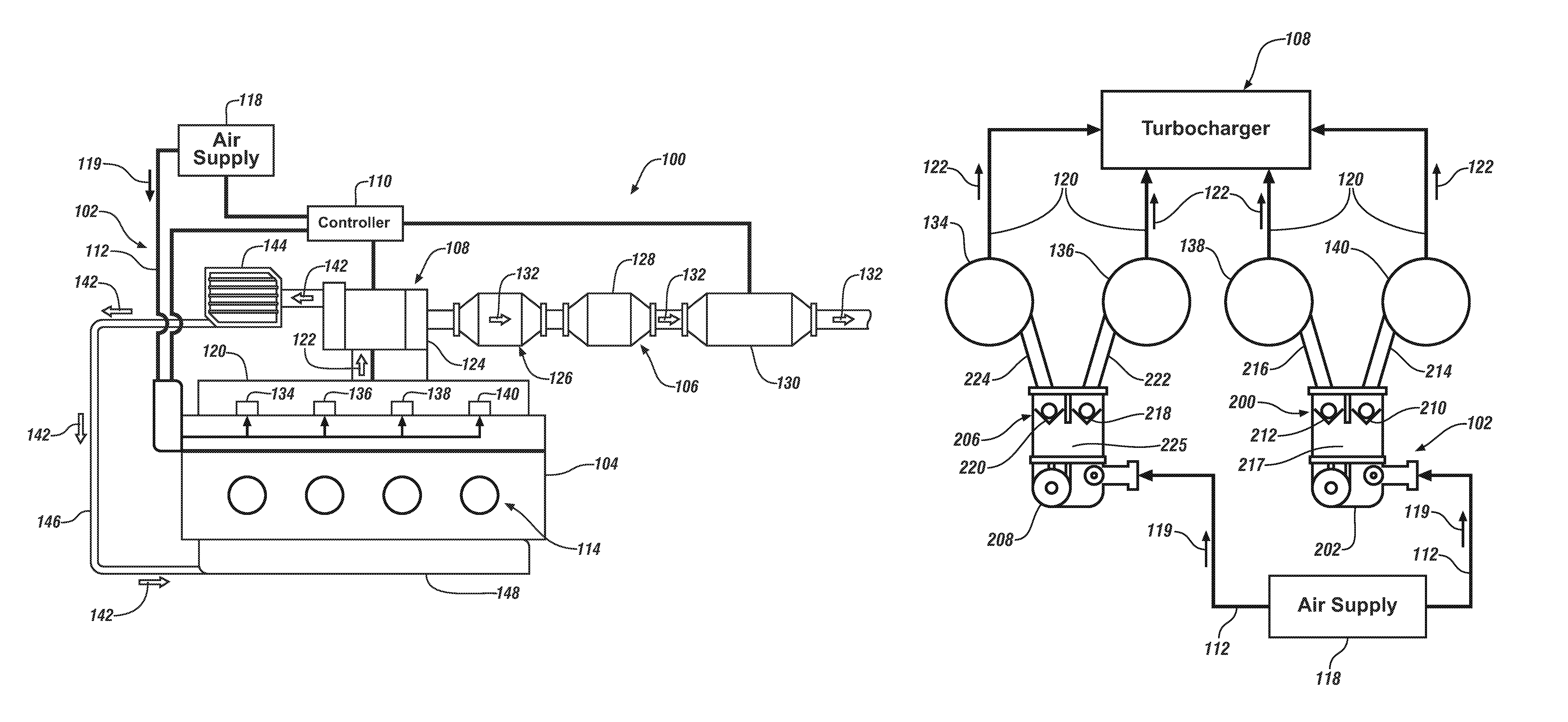
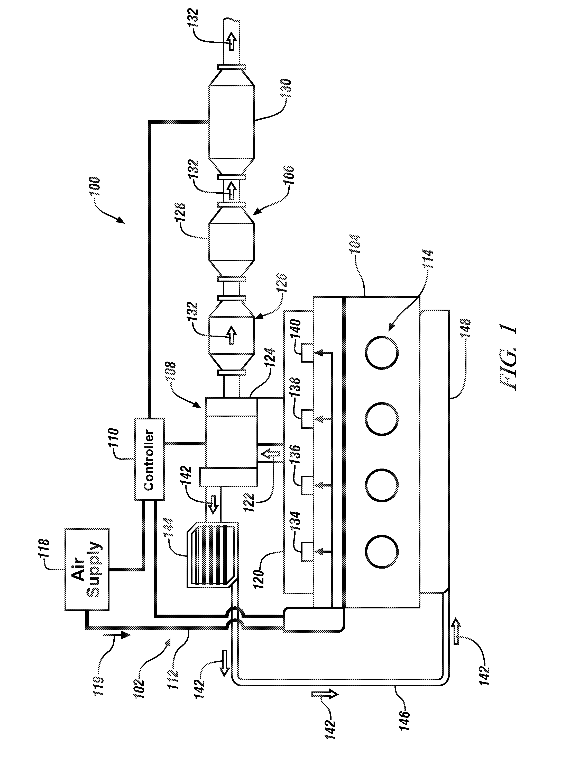
[0012]In accordance with an exemplary embodiment of the invention, FIG. 1 illustrates an exemplary internal combustion engine 100, in this case an in-line four cylinder engine, including a secondary air injection system 102, an engine block and cylinder head assembly 104, an exhaust system 106, a turbocharger 108 and a controller 110. The secondary air injection system 102 includes air supply passages 112 and an air supply 118. Coupled to the engine block and cylinder head assembly 104 is an exhaust manifold 120, which may be integrated with, or external to, the engine block and cylinder head assembly 104. In addition, the engine block and cylinder head assembly 104 includes cylinders 114 wherein the cylinders ...


PUM


Abstract

According to one embodiment of the invention, an internal combustion engine includes a first exhaust port in a cylinder head of the internal combustion engine, a first one way valve coupled to a secondary air system, the first one way valve configured to restrict fluid communication from the first exhaust port to the secondary air system. The engine also includes a second exhaust port in the cylinder head and a second one way valve coupled to the secondary air system, the second one way valve configured to restrict fluid communication from the second exhaust port to the secondary air system, wherein the first and second exhaust ports are in fluid communication with a turbocharger.

Description

FIELD OF THE INVENTION[0001]The subject invention relates to internal combustion engines, and, more particularly, to secondary air injection systems for internal combustion engines.BACKGROUND[0002]An engine control module of an internal combustion engine controls the mixture of fuel and air supplied to combustion chambers of the engine. After the spark plug ignites the air / fuel mixture, combustion takes place and later the combustion gases exit the combustion chambers through exhaust valves. The combustion gases are directed by an exhaust manifold to a catalytic converter or other exhaust after treatment systems.[0003]During certain engine operating periods, combustion gases that enter the exhaust manifold are not completely burned. The combustion gases will continue to burn in the exhaust manifold if a sufficient amount of oxygen is available. Secondary air injection systems are used to inject additional air into the exhaust flow to allow combustion to continue, which improves the ...

Claims


Application Information

Patent Timeline
Patent Type & Authority Patents(United States)
IPC IPC(8): F02B33/44F02B37/02F01N3/00F02B37/12F01N3/34
CPCF01N3/34F02B37/02F02B37/025Y02T10/144Y02T10/20Y02T10/12
Inventor JACQUES, ROBERT LIONELKRIDNER, KENNETH R.
Owner GM GLOBAL TECH OPERATIONS LLC
Why Eureka
Try Eureka