Forwardly directed fluid jet crossing catheter

a technology of fluid jet and catheter, which is applied in the field of catheters, can solve the problems of increasing radiation exposure to patients, not being reliable, and not being mature enough to meet the needs of patients, and achieves the effect of effective penetration

Active Publication Date: 2015-03-10
BOSTON SCI MEDICAL DEVICE LTD
View PDF113 Cites 9 Cited by
  • Summary
  • Abstract
  • Description
  • Claims
  • Application Information

AI Technical Summary

Benefits of technology

[0007]The general purpose of the present invention is to provide a forwardly directed fluid jet crossing catheter. The forwardly directed fluid jet crossing catheter uses a single saline fluid jet stream, preferably in tubular flow form and / or in solid flow form, to penetrate and advance through a chronic total occlusion. The concept for the present invention stemmed from vessel safety testing that had been done with thrombectomy catheters. Collective findings of numerous animal studies have shown that the side exhaust flow velocities from thrombectomy catheters were safe although the internal fluid jet streams were so fast that they could possibly damage an artery when it was contacted. Thrombectomy catheters, using cross stream jet technology, have two distinct sets of windows (or orifices). There is one set of inflow windows that is near the origin of the internal high velocity fluid jet streams and another set of side exhaust windows that is located proximally. The concept behind the forwardly directed fluid jet crossing catheter, which can also be referred to as a front spray catheter, is to provide a velocity that is less than the high velocity fluid jets of thrombectomy catheters that will still be safe for contacting the vessel wall, and yet higher than the side exhaust velocity of thrombectomy catheters so that it will be efficacious in penetrating through a tough organized clot.
[0011]One significant aspect and feature of the forwardly directable fluid jet crossing catheter is a minimal reduced distal cross section in order to enhance the ability to cross chronic total occlusions in small or narrow vascular regions.
[0013]Still another significant aspect and feature of the present invention is a formable and shapeable catheter tip region having a section of annealed high pressure tube within a distal catheter tube and a flexible tapered tip providing a directable and shapeable atraumatic tip where such formable and shapeable catheter tip region can positively influence tracking along the vasculature.
[0014]Still another significant aspect and feature of the present invention is a forwardly directed fluid jet crossing catheter with a flexible tapered tip that gradually transitions substantially to the diameter of a guidewire to aid in tracking and in crossing a chronic total occlusion.

Problems solved by technology

As such, the field is not mature with products that are proven in this challenging task, especially for chronic total occlusions in a coronary artery.
However, the use of this type of stiff wire for chronic total occlusions is challenging and time consuming resulting in an increased radiation exposure to the patient.
This device was unsuccessful some of the time so it was not seen as being reliable.
Although this system is considered generally reliable by trained professionals, it has some limitations.
First, the method is slow.
Second, if a channel is burned next to the vessel wall, it can be difficult to direct the wire to take an alternative path.
Although this is a novel technique, it is not uniformly accepted, nor is this type of procedure comfortable for physicians to perform.

Method used


Image

  • Forwardly directed fluid jet crossing catheter
  • Forwardly directed fluid jet crossing catheter
  • Forwardly directed fluid jet crossing catheter

Examples


Embodiment Construction

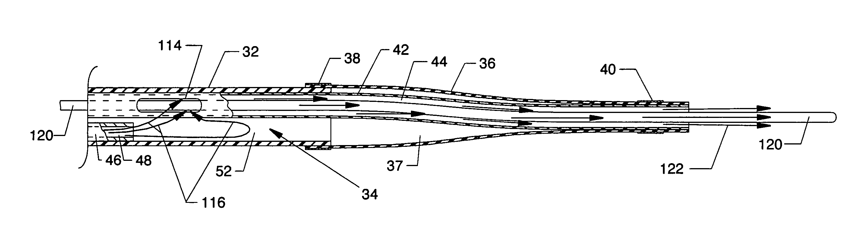
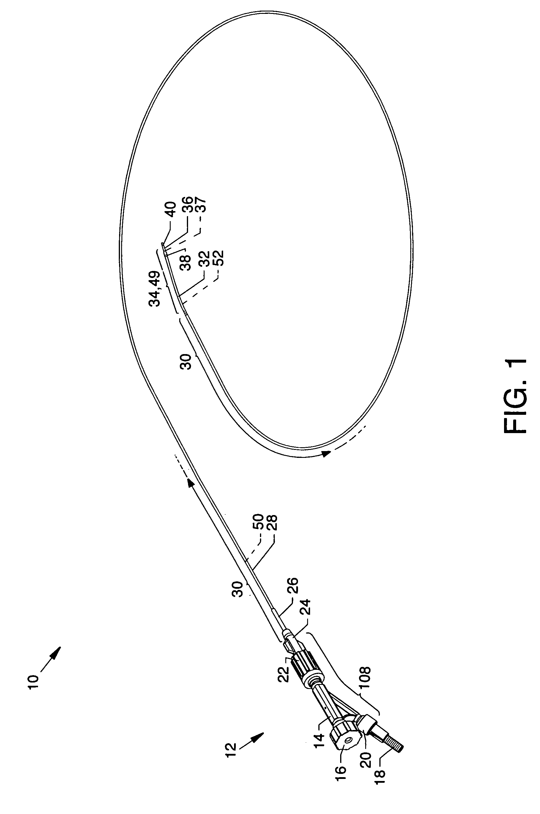
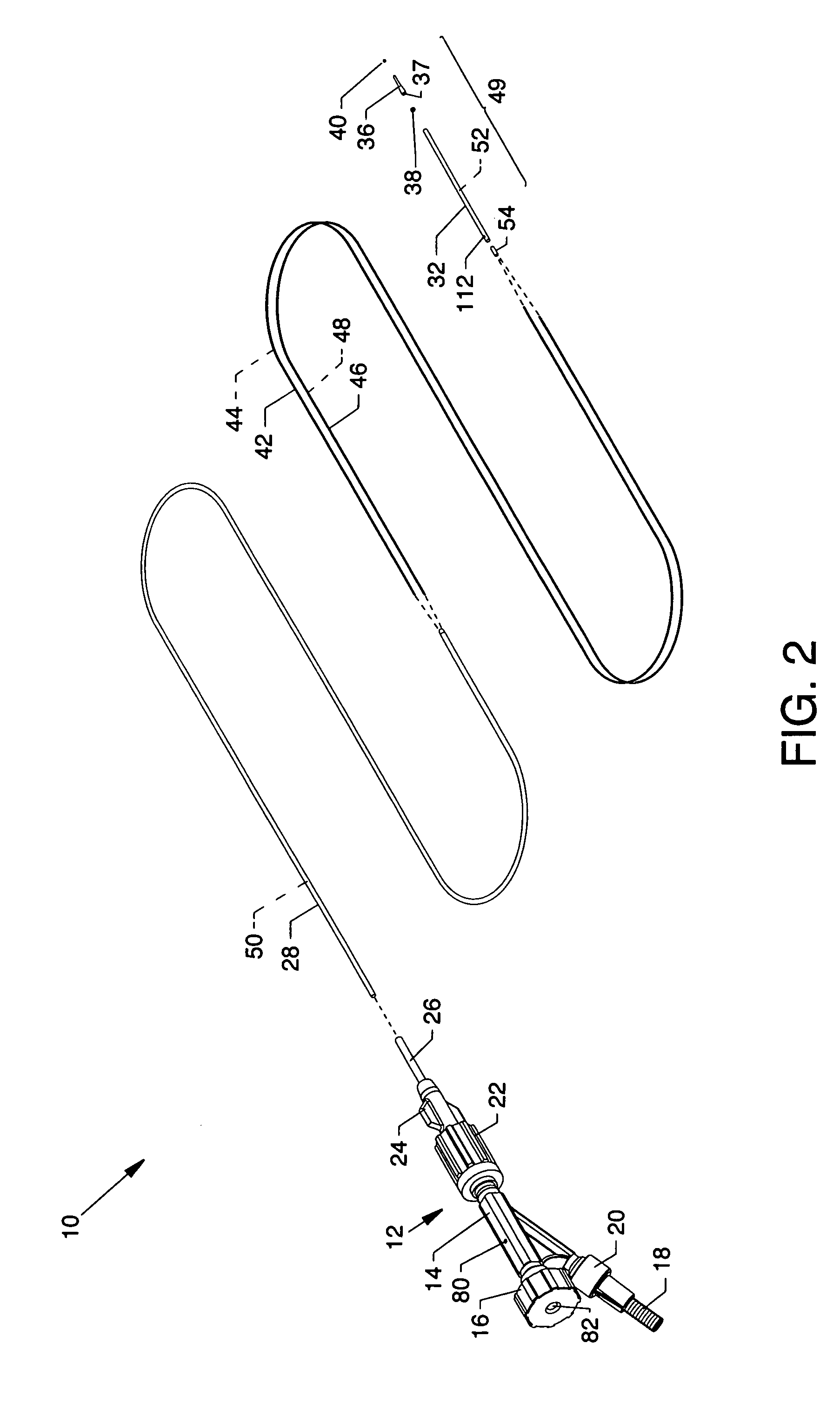
[0042]FIG. 1 is an isometric view of a forwardly directed fluid jet crossing catheter 10, the present invention, and FIG. 2 is an isometric view of the invention where the components distal to a manifold 12 are shown in exploded view. Readily identifiable components at the proximal region of the invention include, but are not limited to, the manifold 12 having closely associated components including a central body 14, a hemostasis valve 16, a high pressure connector 18, a Luer fitting 20, a Luer connector 22, a winged Luer fitting 24, and a strain relief tube 26. Other components of the invention extend from the interior of the manifold 12 and through the strain relief tube 26 in succession in a distal direction including, but not limited to, a torqueable and flexible (4 French) proximal catheter tube 28, preferably of Pebax®, which, in general, delineates the greater portion of a low pressure cavity 30 (FIG. 1), another torqueable and short reduced diameter flexible and shapeable l...


PUM


Abstract

A forwardly directed fluid jet crossing catheter having a distally directed cylindrical flow fluid jet stream to cross a chronic total occlusion is set forth. The distal end of the device includes a formable catheter tip region having flexible internal components. Low and high pressure cavities are formed substantially by joined proximal and distal catheter tubes having an adhesive plug seal in common therebetween which partially defines one end of each of the low pressure and high pressure cavities. A guidewire tube and a high pressure tube are aligned along and within the low pressure and high pressure cavities and through the adhesive plug seal. The high pressure tube openly terminates in the high pressure cavity, whereby pressurized fluid transfers from the high pressure cavity in the guidewire tube entry hole to subsequently pass along the guidewire lumen and co-located guidewire to exit as a cylindrical fluid jet stream.

Description

CROSS REFERENCES TO RELATED APPLICATIONS[0001]This application claims priority from the earlier filed U.S. Provisional Application No. 60 / 934,284 filed Jun. 12, 2007, entitled “Front Spray Catheter”, and is hereby incorporated into this application by reference as if fully set forth herein.BACKGROUND OF THE INVENTION[0002]1. Field of the Invention[0003]The present invention relates to the field of catheters, and more particularly, relates to a forwardly directed fluid jet crossing catheter used for the purpose of crossing a Chronic Total Occlusion (CTO), whereby a moderate speed and safe velocity fluid jet stream is used to wear away arterial lesions forming a CTO and advance therethrough. Chronic total occlusions are arterial lesions that have progressed to the point where there is no flow through the vessel (total occlusion). Furthermore, it is generally considered highly difficult to cross a CTO with a standard support guidewire. In other words, if a total occlusion is easily cro...

Claims


Application Information

Patent Timeline
Patent Type & Authority Patents(United States)
IPC IPC(8): A61M5/178A61B17/3203
CPCA61B17/32037A61B2017/32032
Inventor BONNETTE, MICHAEL J.MORRIS, DAVID B.THOR, ERIC J.
Owner BOSTON SCI MEDICAL DEVICE LTD
Why Eureka
Try Eureka