Method of producing optical film laminate

Active Publication Date: 2015-03-10
NITTO DENKO CORP
View PDF45 Cites 2 Cited by
  • Summary
  • Abstract
  • Description
  • Claims
  • Application Information

AI Technical Summary

Benefits of technology

The patent describes a way to make an optical film laminate that prevents curling and other defects when attached to an optical cell. This is done by stretching and dyeing a resin layer on a resin substrate to form a thin polarizing film. The result is an improved quality optical film laminate that is easier to use and more effective in its performance.

Problems solved by technology

Accordingly, in some cases, undesired curling occurs in an optical film laminate to be obtained and inconveniences (such as air bubbles and wrinkles) occur when the optical film laminate is attached to an optical cell such as a liquid crystal cell later.
In particular, the problem tends to be additionally remarkable when one of the protective films also serves as an optical compensation film or an antireflection retardation film (typically a λ / 4 plate) for thinning the optical film laminate.

Method used


Image

  • Method of producing optical film laminate
  • Method of producing optical film laminate
  • Method of producing optical film laminate

Examples


example 1

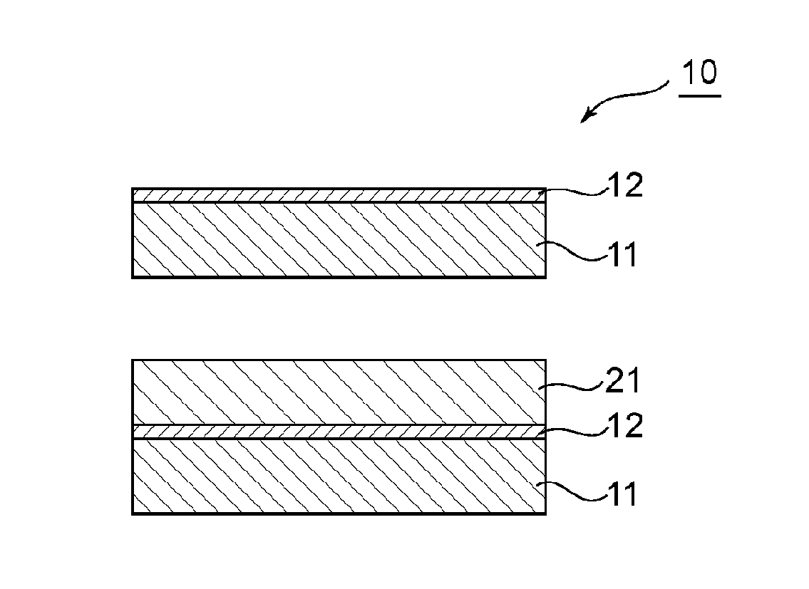
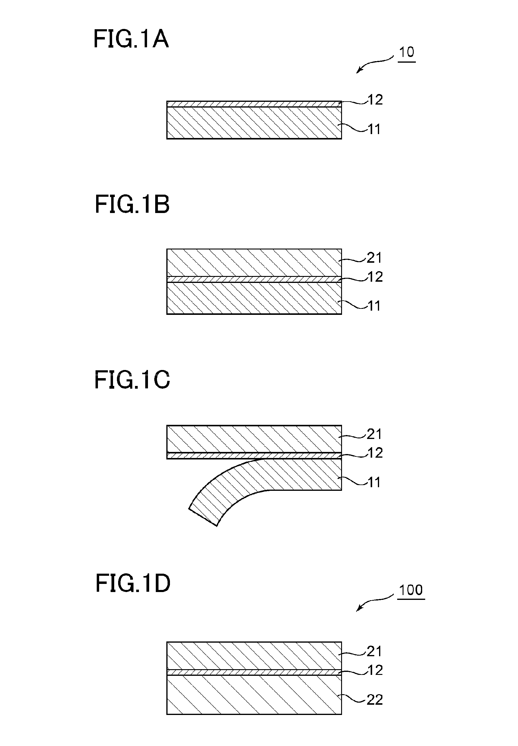
[0085]An amorphous polyethylene terephthalate (A-PET) film (manufactured by Mitsubishi Chemical Corporation, trade name “NOVACLEAR SH046,” thickness: 200 μm) was used as a resin substrate. The surface of the resin substrate was subjected to a corona treatment (58 W / m2 / min).

[0086]Meanwhile, a PVA (polymerization degree: 4,200, saponification degree: 99.2%) to which 1 wt % of an acetoacetyl-modified PVA (manufactured by The Nippon Synthetic Chemical Industry Co., Ltd., trade name “GOHSEFIMER Z200,” polymerization degree: 1,200, saponification degree: 99.0% or more, acetoacetyl modification degree: 4.6%) had been added was prepared and applied to the corona-treated surface of the resin substrate so that its thickness after drying became 12 μm, followed by drying with hot air in an atmosphere at 60° C. for 10 minutes. Thus, a laminate in which a PVA-based resin layer was formed on the resin substrate was produced.

[0087]The resultant laminate was subjected to free-end uniaxial stretching...

example 2

[0096]An optical film laminate was produced in the same manner as in Example 1 except that the thickness of the first protective film (cycloolefin-based film) was changed to 18 μm, its linear expansion coefficient in the feed direction was changed to 80×10−6 / K, and its linear expansion coefficient in the direction perpendicular to the feed direction was changed to 36×10−6 / K. The state of the curling of the resultant optical film laminate was visually observed in the same manner as in Example 1. FIG. 3 shows the state of the curling. The optical film laminate was convex toward the first protective film side, though some degree of curling occurred in the laminate. As a result, when the optical film laminate was attached to a liquid crystal cell while the first protective film was placed on the liquid crystal cell side, the laminate was able to be satisfactorily attached to the liquid crystal cell without the occurrence of inconveniences such as air bubbles and wrinkles.


PUM

PropertyMeasurementUnit
Expansion enthalpyaaaaaaaaaa

Abstract

A method of producing an optical film laminate includes: stretching and dyeing a laminate including a resin substrate and a polyvinyl alcohol-based resin layer formed on one side of the resin substrate to produce a polarizing film on the resin substrate; laminating a first protective film on the polarizing film on an opposite side to the resin substrate; and peeling the resin substrate, followed by laminating a second protective film on the polarizing film on a side from which the resin substrate has been peeled. The first protective film is a protective film to be placed on an optical cell side when the optical film laminate is attached to the optical cell, the second protective film is a protective film to be placed on an opposite side to the optical cell when the optical film laminate is attached to the optical cell.

Description

[0001]This application claims priority under 35 U.S.C. Section 119 to Japanese Patent Application No. 2013-188049 filed on Sep. 11, 2013, which is herein incorporated by reference.BACKGROUND OF THE INVENTION[0002]1. Field of the Invention[0003]The present invention relates to a method of producing an optical film laminate.[0004]2. Description of the Related Art[0005]A polarizing plate is placed on each of both sides of a liquid crystal cell of a liquid crystal display apparatus, which is a typical image display apparatus, the placement being attributable to an image-forming mode of the apparatus. The following method has been known as a method of producing the polarizing plate (for example, Japanese Patent Application Laid-open No. Hei 11-179871). A protective film is placed on each of both sides of a polarizer, and then the protective films are attached to both sides of the polarizer by continuously passing the polarizer and the protective films through a pair of rolls while supply...

Claims


Application Information

Patent Timeline
IPC IPC(8): G02B5/30B32B37/14
CPCG02B5/3025B32B37/14B32B37/144B32B2457/20
Inventor KITAGAWA, TAKEHARUYASEN, MUNIRIDIN
Owner NITTO DENKO CORP
Why Eureka
Try Eureka