Muffle tube inspection method and manufacturing method of silica glass-based optical fiber preform

a manufacturing method and technology of silica glass, applied in the direction of fluid tightness measurement, manufacturing tools, instruments, etc., can solve the problems of deterioration of the transmission characteristics of the optical fiber manufactured by fiber drawing from the resultant transparent glass body, loss of safety or workability, and failure to detect cracks in the muffle tube, so as to improve the process yield and reliably detect cracks.

Active Publication Date: 2015-03-17
FUJIKURA LTD
View PDF9 Cites 0 Cited by
  • Summary
  • Abstract
  • Description
  • Claims
  • Application Information

AI Technical Summary

Benefits of technology

[0036]According to the above-described muffle tube inspection method related to the first aspect of the invention, it is possible to detect a crack generated at a muffle tube by making the inner pressure of the muffle tube high with the intention thereof.
[0037]Furthermore, since the crack generated at a muffle tube is detected by action of variation in the inner pressure of the furnace body disposed around the periphery of the muffle tube, it is possible to reliably detect a crack generated at a muffle tube without visually checking the muffle tube.
[0038]Therefore, since it is not necessary to use a cracked muffle tube in the step of dehydrating and sintering a preform, it is possible to improve a process yield without wasting a preform (porous preform).

Problems solved by technology

Because of this, transmission characteristics of the optical fiber manufactured by fiber drawing from the resultant transparent glass body becomes deteriorated.
Additionally, in the case of using a halogen series gas such as chlorine, fluorine, or the like, if the gas leaks outside the muffle tube 102, safety or workability loses.
However, there is a concern that muffle tube is cracked not only when the dehydration and sintering is carried out but also when the muffle tube is cooled down after completion of sintering the porous preform, or due to an external factor such as an earthquake or the like.
Particularly, in the muffle tube, the portion surrounded by the heater, at which difference in temperature between the case of performing dehydration and sintering and the case of not performing dehydration and sintering is large, is easily cracked.
If the dehydration and sintering step begins without being aware of a cracked muffle tube, there are problems in that, as above-described, a dehydration defect in the porous preform occurs in the dehydration and sintering step or impurities generated from the heater or the like is introduced into the porous preform.

Method used


Image

  • Muffle tube inspection method and manufacturing method of silica glass-based optical fiber preform
  • Muffle tube inspection method and manufacturing method of silica glass-based optical fiber preform
  • Muffle tube inspection method and manufacturing method of silica glass-based optical fiber preform

Examples


first embodiment

(1) First Embodiment

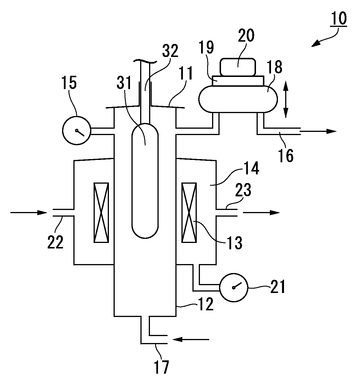
[0044]FIG. 1 is a schematic diagram illustrating a muffle tube inspection method related to a first embodiment of the invention and a sintering furnace used in a manufacturing method of a silica glass-based optical fiber preform related to a first embodiment of the invention.

[0045]The sintering furnace 10 is substantially configured to include a removable lid 11, a muffle tube 12 made of silica glass, a heater 13 disposed around the periphery of the muffle tube 12, and a furnace body 14 which is disposed around the periphery of the muffle tube 12 and covers the heater 13 so as to shut external air out.

[0046]An inner-pressure gauge 15 measuring the inner pressure and a gas exhaust 16 discharging a gas from the inside thereof are provided at an upper portion of the muffle tube 12.

[0047]In addition, at a bottom portion of the muffle tube 12, a gas supply port 17 communicated with the inside thereof is provided.

[0048]A balloon-shaped pressure-adjustment device 18 is ...

second embodiment

(2) Second Embodiment

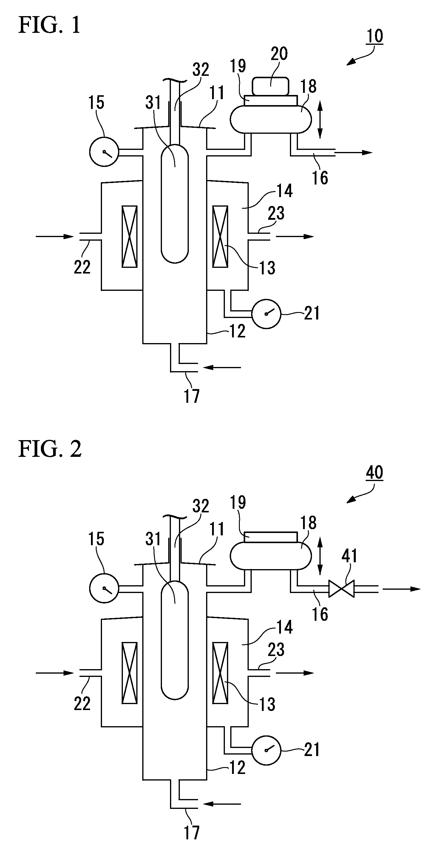
[0081]FIG. 2 is a schematic diagram illustrating a muffle tube inspection method related to a second embodiment of the invention and a sintering furnace used in a manufacturing method of a silica glass-based optical fiber preform related to a second embodiment of the invention.

[0082]In FIG. 2, identical symbols are used for the constituent elements which are identical to the constituent elements of the first embodiment shown in FIG. 1, and the explanations thereof are omitted or simplified.

[0083]A sintering furnace 40 of the embodiment is different from the above-described sintering furnace 10 in that the inside-pressure increasing weight 20 is not used and a valve 41 is provided at the midstream the gas exhaust 16 of the muffle tube 12.

[0084]As the valve 41, a needle valve, a ball valve, a gate valve, a glove valve, or the like is used.

[0085]In the above valves, a needle valve is preferably used because adjustment of the flow rate is easy.

[0086]In the muffle tu...

third embodiment

(3) Third Embodiment

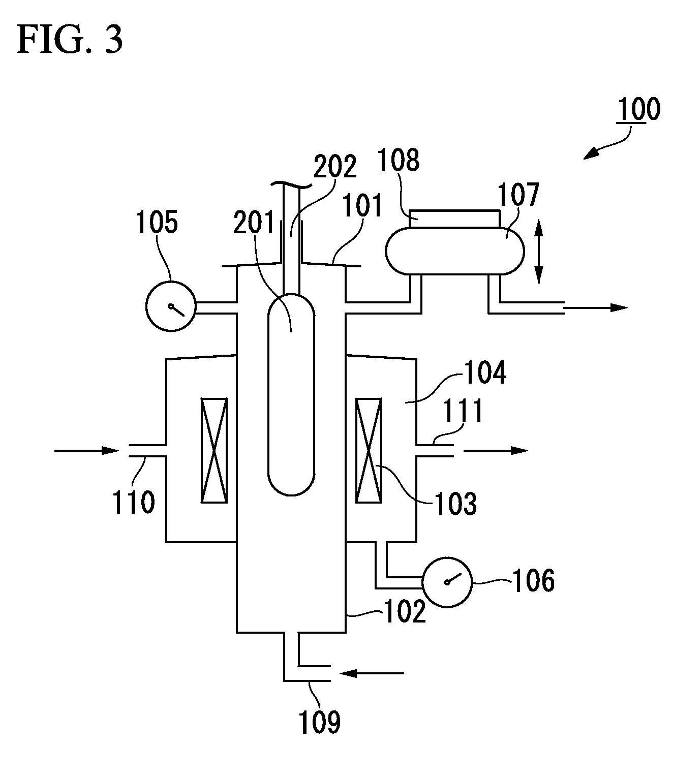
[0095]In the muffle tube inspection method of the embodiment, the sintering furnace which is the same as the sintering furnace as show in, for example, FIG. 1 or FIG. 2 is used, the pressure inside the muffle tube 12 is varied by adjusting the amount of the inert gas which is supplied to the muffle tube 12 by a mass-flow controller (not shown in the figure) provided at the gas supply port 17 of the muffle tube 12, the inner pressure of the furnace body 14 is measured using the inner-pressure gauge 21 at this time, and a crack of the muffle tube 12 is thereby detected.

[0096]That is, the flow rate of the inert gas flowing in the muffle tube 12 increases by use of the mass-flow controller, the inner pressure of the muffle tube 12 becomes high, and a crack of the muffle tube 12 is thereby detected.

[0097]The mass-flow controller electrically measures the flow rate of the inert gas and controls the flow rate thereof.

[0098]However, since it is only necessary to control ...


PUM

PropertyMeasurementUnit
temperatureaaaaaaaaaa
pressureaaaaaaaaaa
pressureaaaaaaaaaa

Abstract

A muffle tube inspection method inspects a muffle tube used for dehydrating and sintering a silica glass-based optical fiber preform, the muffle tube includes a sintering furnace provided with a furnace body covering a heater disposed around a periphery of the muffle tube. The method detects a crack generated at the muffle tube by measuring a pressure inside the furnace body while varying a pressure inside the muffle tube.

Description

CROSS REFERENCE TO RELATED APPLICATIONS[0001]This application is a continuation application based on a PCT Patent Application No. PCT / JP2011 / 065004, filed Jun. 30, 2011, whose priority is claimed on Japanese Patent Application No. 2010-149159, filed Jun. 30, 2010, the entire content of which are hereby incorporated by reference.BACKGROUND OF THE INVENTION[0002]1. Field of the Invention[0003]The present invention relates to a muffle tube inspection method for detecting a crack generated at a muffle tube constituting a sintering furnace performing dehydration and sintering when manufacturing a silica glass-based optical fiber preform, and a manufacturing method of a silica glass-based optical fiber preform including an inspection step using the inspection method.[0004]2. Description of the Related Art[0005]Generally, a silica glass-based optical fiber is manufactured in a manner such that a porous preform produced by a VAD (Vapor phase Axial Deposition) method or an OVD (Outside Vapor...

Claims


Application Information

Patent Timeline
Patent Type & Authority Patents(United States)
IPC IPC(8): C03B37/014C03B37/012G01M3/28
CPCC03B37/0146G01M3/2846Y02P40/57
Inventor ENDO, SHO
Owner FUJIKURA LTD
Why Eureka
Try Eureka