

Bicycle disc brake rotor
a technology of disc brake rotor and bicycle, which is applied in the direction of braking disc, cycle brake, cycle equipment, etc., can solve the problems of generating a substantial amount of heat in and achieve the effect of promoting cooling of the disc brake rotor and excellent performan
- Summary
- Abstract
- Description
- Claims
- Application Information
AI Technical Summary
Benefits of technology
Problems solved by technology
Method used
Image

Examples
first embodiment
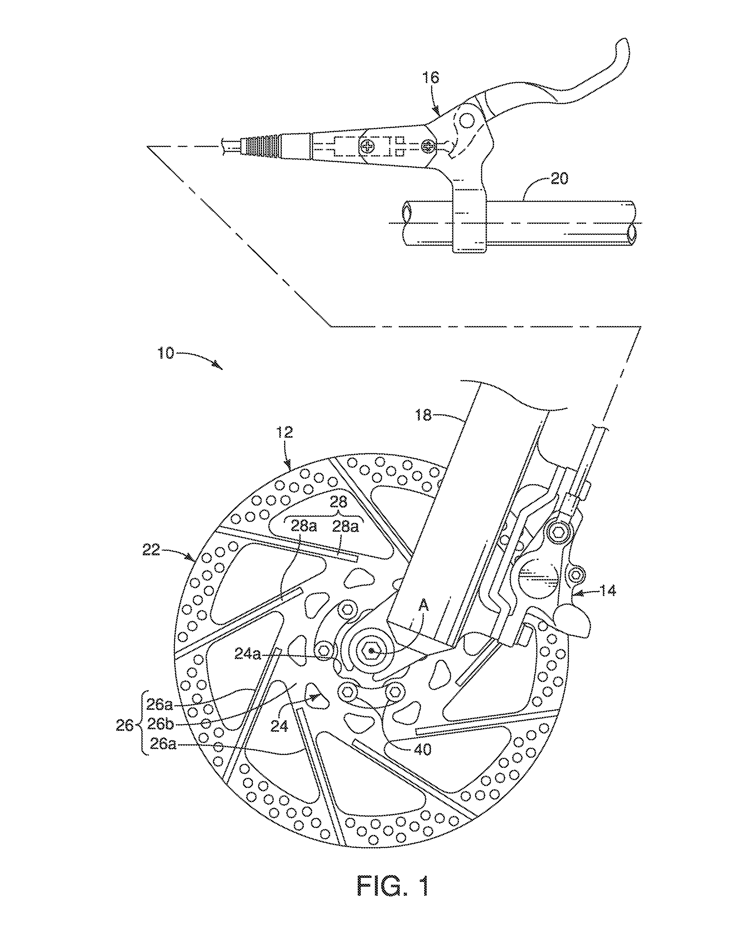
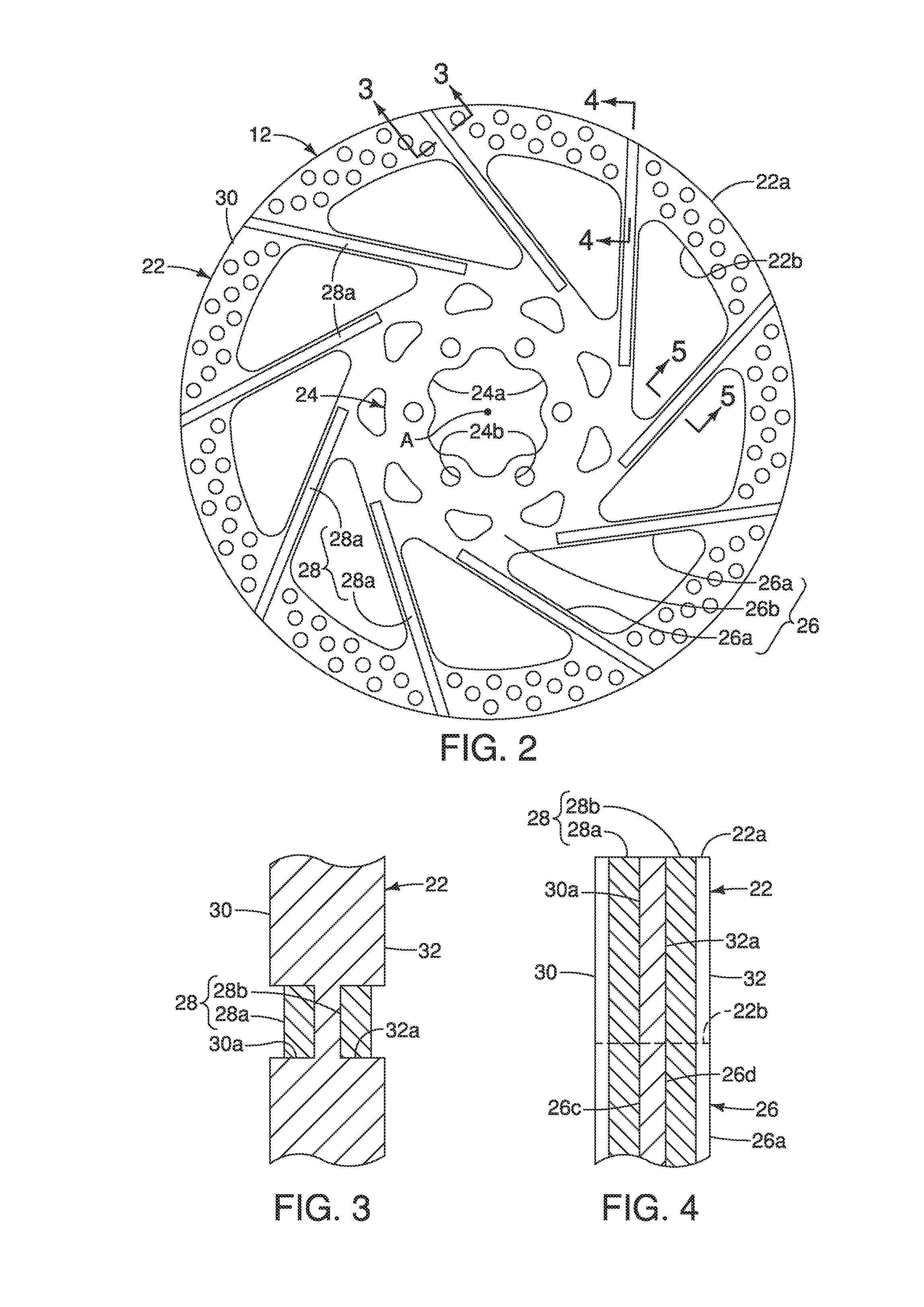
[0026]Referring initially to FIG. 1, a front disc brake system 10 is illustrated that includes a bicycle disc brake rotor 12 in accordance with a As explained below, the bicycle disc brake rotor 12 has a configuration that promotes cooling of the bicycle disc brake rotor 12. The front disc brake system 10 further includes a bicycle disc brake caliper 14 and a brake operating (actuating) mechanism 16. Basically, the bicycle disc brake rotor 12 is fixedly attached to a hub (not shown) of a bicycle wheel (not shown). The bicycle disc brake caliper 14 is mounted to a bicycle fork 18, while brake operating mechanism 16 is attached to a bicycle handlebar 20. Since the operation and construction of the front disc brake system 10 is conventional, except for the construction of the bicycle disc brake rotor 12, the front disc brake system 10 will not be discussed or shown in further detail herein. Moreover, while the front disc brake system 10 is illustrated as a hydraulic braking system, th...
second embodiment
[0033]Referring now to FIG. 6, a bicycle disc brake rotor 112 in accordance with a second embodiment will now be explained. The bicycle disc brake rotor 112 basically has an outer portion 122, an inner portion 124 and an intermediate portion 126. The intermediate portion 126 is disposed between the outer portion 122 and the inner portion 124 and interconnects the outer portion 122 and the inner portion 124 together. The outer portion 122 and the intermediate portion 126 are integrally formed as a one-piece member of the first material. The inner portion 124 is a separate member that is fixed to the inner end of the intermediate portion 126 by fasteners such as the rivets 140 as illustrated. The inner portion 124 has a hub mounting opening 124a that has a plurality of serrations.
[0034]The layer 128 is made of a second material (e.g., copper) that is different from the first material (e.g., stainless steel). Preferably, the material of the layer 128 has a higher thermal conductivity t...
third embodiment
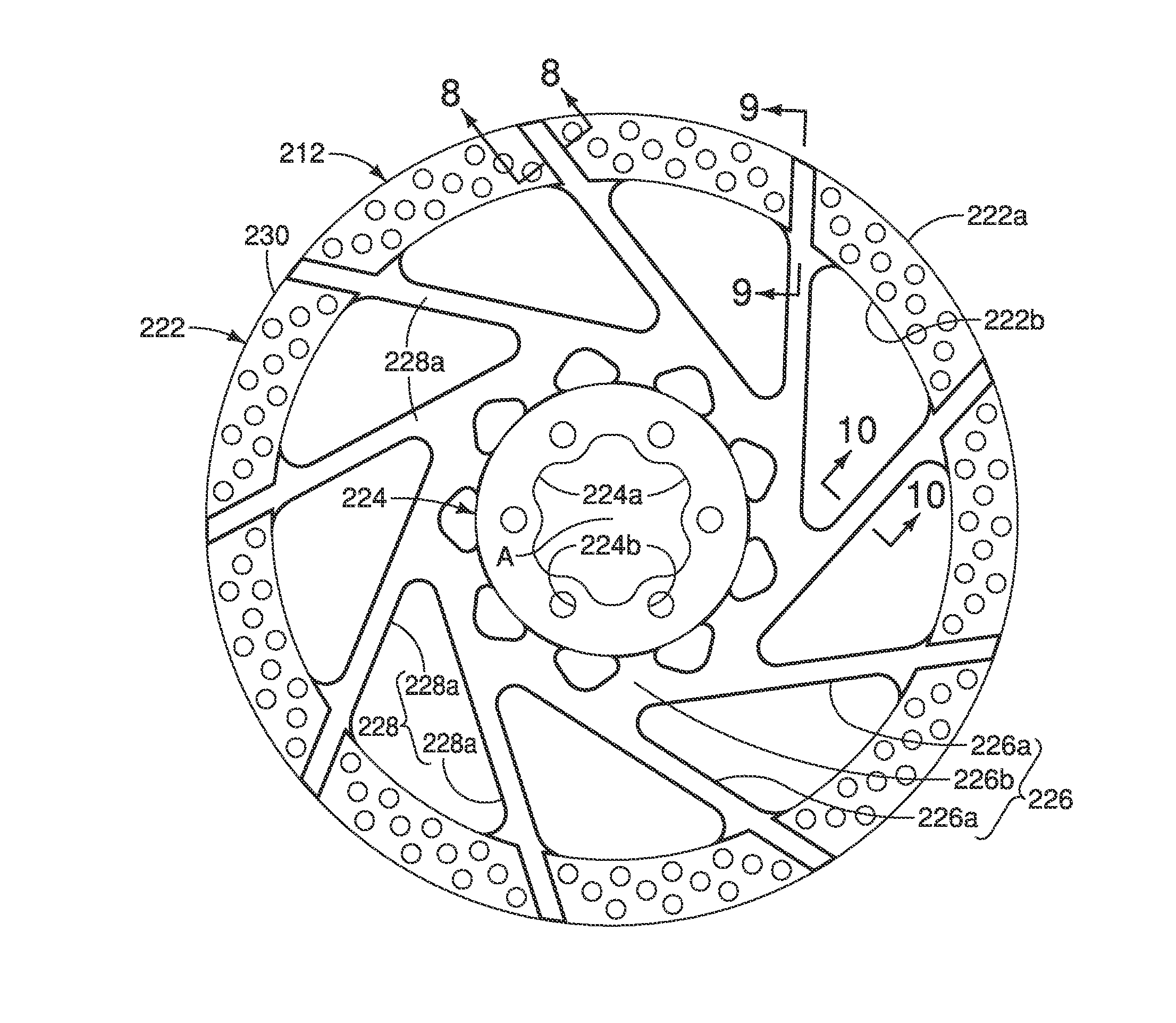
[0035]Referring now to FIGS. 7 to 10, a bicycle disc brake rotor 212 in accordance with a third embodiment will now be explained. The bicycle disc brake rotor 212 basically has an outer portion 222, an inner portion 224 and an intermediate portion 226. The bicycle disc brake rotor 212 is basically identical to the bicycle disc brake rotor 12, as discussed above, except that each side of the intermediate portion 226 is completely laminated by a layer 228 and the recesses have been eliminated in the intermediate portion 226. The periphery of the layer 228 is indicated by a thicker line in FIG. 7. The layer 228 overlies sections of friction braking surfaces 230 and 232 of the outer portion 222. The layer 228 is made of a second material (e.g., copper) that is different from the first material (e.g., stainless steel) of the outer portion 222, the inner portion 224 and the intermediate portion 226. Preferably, the material of the layer 228 has a higher thermal conductivity than the mater...
PUM
| Property | Measurement | Unit |
|---|---|---|
| friction | aaaaa | aaaaa |
| braking force | aaaaa | aaaaa |
| rotation | aaaaa | aaaaa |
Abstract
Description
Claims
Application Information