Cable termination device, a method for prefabricating a cable termination device and a method for achieving a cable termination

a cable termination and prefabrication technology, applied in the direction of cable termination, overhead line/cable apparatus, insulating body, etc., can solve the problems of sudden changes in the cable shielding system, increased labor intensity, and increased cost, so as to achieve simple and safe manner

Active Publication Date: 2015-03-17
NKT HV CABLES AB
View PDF10 Cites 1 Cited by
  • Summary
  • Abstract
  • Description
  • Claims
  • Application Information

AI Technical Summary

Benefits of technology

[0011]An advantage with having two deflectors on the stress controller device is that the stress controller device may be made shorter than a conventional conical stress controller device having only one deflector, and that this it is less complicated to manufacture than the much longer conventional conical stress controller devices. It is also easier to insert the cable when the stress controller device is shorter.
[0027]The stress controller device and the surrounding electrically insulating gel may also form a compressible unit which can adapt to different cable diameters. Generally, the compressibility will also facilitate the insertion of the cable into the stress controller device and the entire cable termination device.

Problems solved by technology

In particular, electric stress occurs at sudden changes in the cable shielding system, e.g. where a semi-conducting outer layer is cut away.
The assembling work at site is a time consuming procedure with a medium such as oil that is unfriendly to the environment.
There are risks involved, for example if the cable termination should explode the damage would be severe with burning oil.
The existing dry types of cable termination devices have the main drawback of being expensive.

Method used


Image

  • Cable termination device, a method for prefabricating a cable termination device and a method for achieving a cable termination
  • Cable termination device, a method for prefabricating a cable termination device and a method for achieving a cable termination
  • Cable termination device, a method for prefabricating a cable termination device and a method for achieving a cable termination

Examples


Embodiment Construction

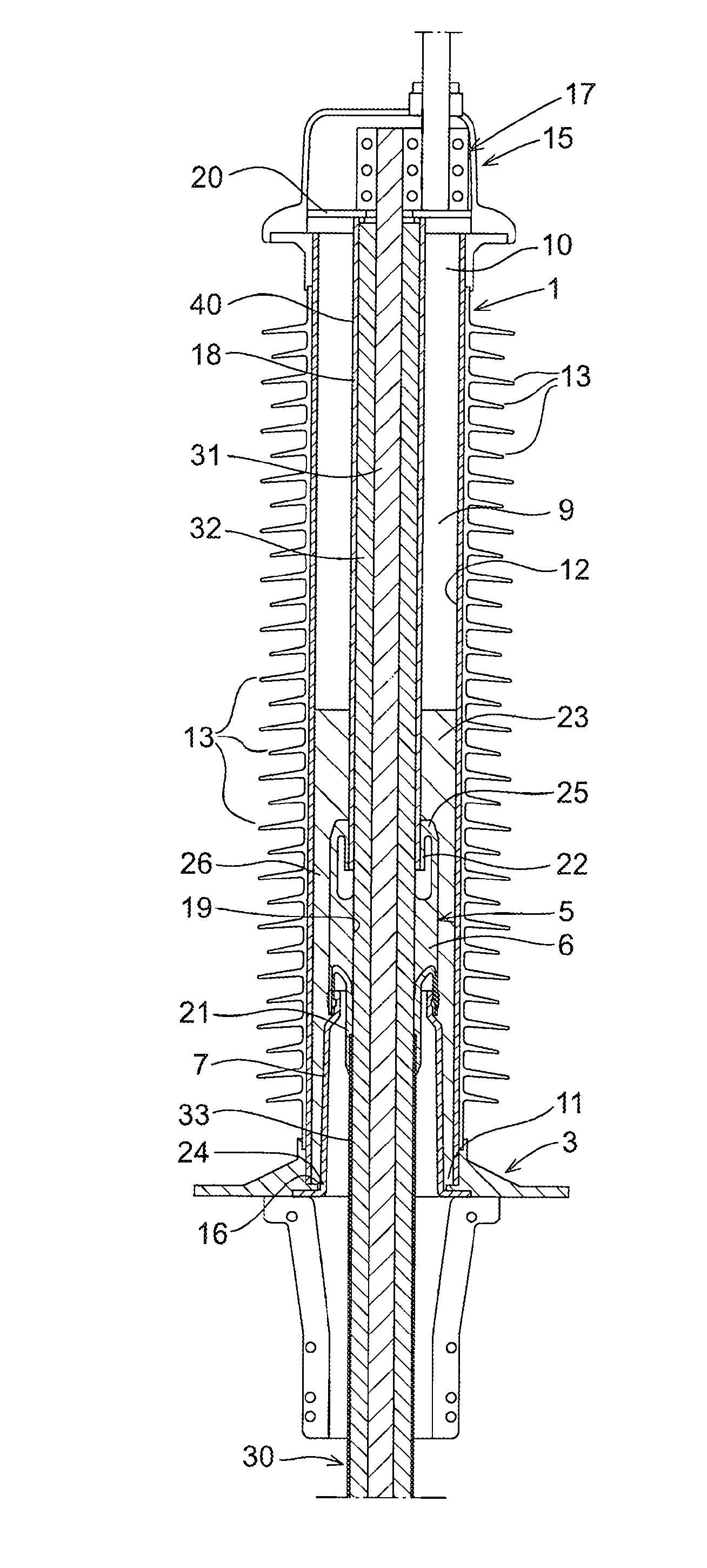
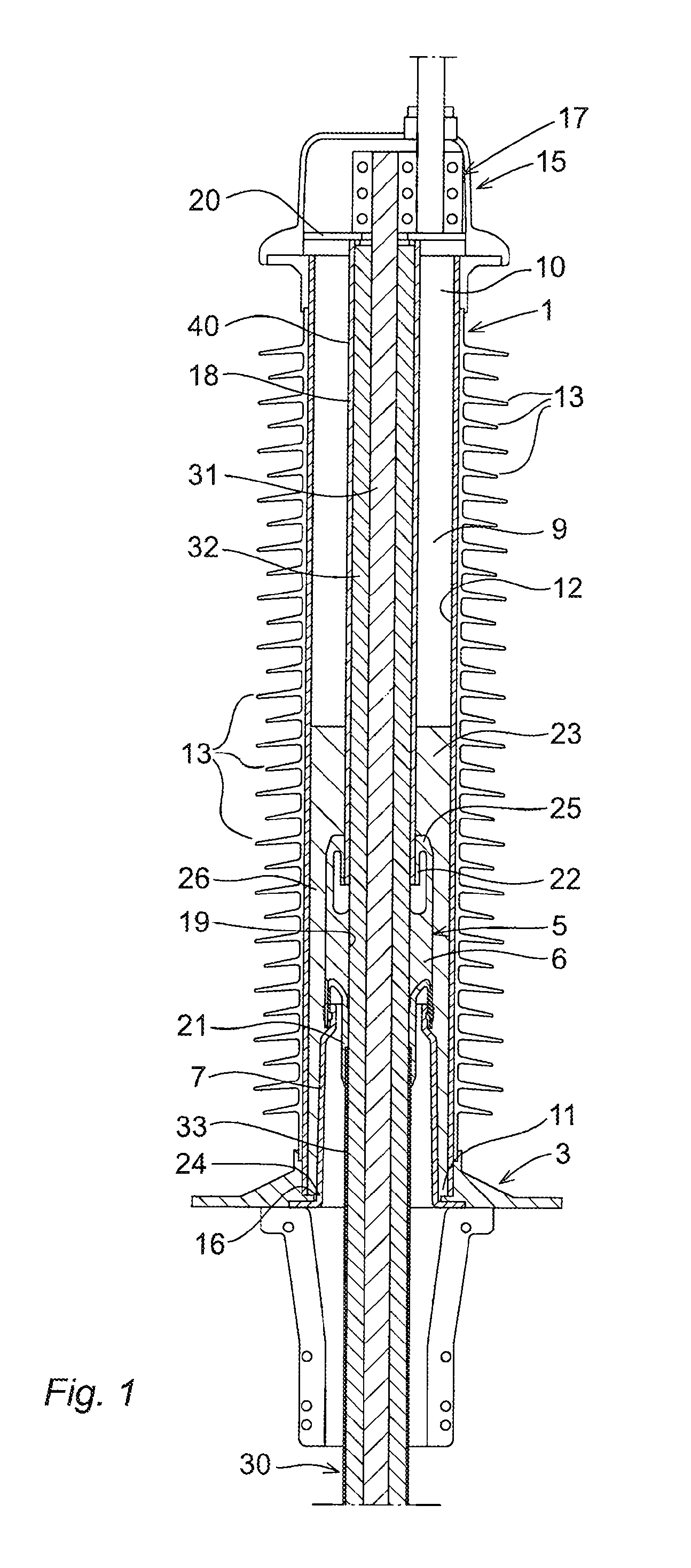
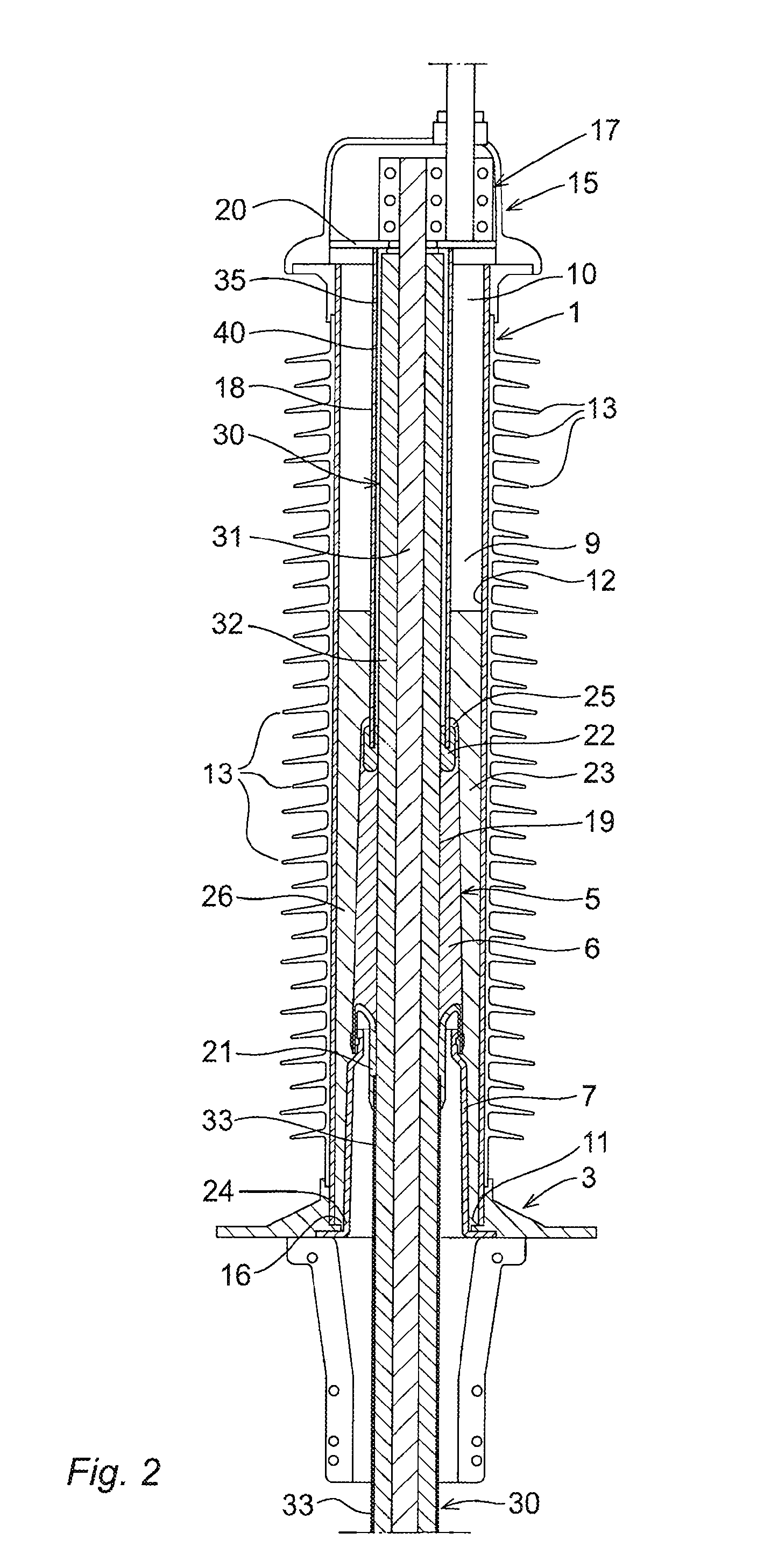
[0047]The cable termination device, according to the present invention, of which an embodiment is shown in FIG. 1, comprises an insulator housing 1, including a base member 3, and a stress controller device 5. The stress controller device 5 in the illustrated example comprises a stress control member or stress cone 6, and an intermediate support pipe 7. The stress control member 6 is mounted on the intermediate support pipe 7, which in turn is mounted on the base member 3 of the insulator housing. The stress controller device 5 is located inside the insulator housing 1. The insulator housing 1 has a hollow interior 9, and it has two open ends, an upper end forming a first end 10 and a lower end forming a second end 11. Usually, the shape of the insulator housing is basically cylindrical with a central bore 12 forming an inner wall of the insulator housing, sometimes with a tapering at one or both the ends. The insulator housing may be provided with a series of skirts 13 on its exter...


PUM

PropertyMeasurementUnit
electric voltagesaaaaaaaaaa
angleaaaaaaaaaa
voltageaaaaaaaaaa

Abstract

A cable termination device of the dry type, for terminating a high voltage cable, including an insulator housing with a first end and a second end and having a hollow interior, and which second end has an opening for insertion of a high voltage cable. The cable termination device further includes a stress controller device located inside the insulator housing and adapted to be mounted on a high voltage cable, an end cap located at the first end of the insulator housing and provided with an external electrical connection means, and an electrically insulating gel filling at least part of the hollow interior of the insulator housing and surrounding at least part of the stress controller device. Further, the stress controller device is provided with a first and a second deflector arrangement for controlling an electric field.

Description

FIELD OF THE INVENTION[0001]The present invention relates to a cable termination device of the dry type, and a method for achieving a cable termination on a cable, such as a high voltage cable. In particular, the present invention relates to terminations for electric cables used for electric power distribution.BACKGROUND OF THE INVENTION[0002]Cables used for electric power distribution are typically operated at thousands of volts, and consequently care must be taken when terminating these cables and connecting them to electrical components, e.g. switchgear units. At the point where the cable is terminated electrical stress occurs that needs to be controlled.[0003]The cable termination typically requires that various dielectric, insulation, semi-conducting and conductive shield layers that surrounds the central current carrying conductor are removed, and that the various semi-conducting and conducting surrounding layers are appropriately connected to the involved electrical equipment...

Claims


Application Information

Patent Timeline
Patent Type & Authority Patents(United States)
IPC IPC(8): H02G15/02H02G1/04H02G7/05H02G15/04H02G15/064
CPCH02G7/05H02G1/04H02G15/064H02G15/046Y10T29/49117H02G15/04
Inventor BOHLIN, AKERAPP, HANSSVAHN, JORGENPURIN, MARTINMARTENSSON, DANIEL
Owner NKT HV CABLES AB
Why Eureka
Try Eureka