Rotor disc with axial retention of the blades, assembly of a disc and a ring, and turbomachine

A technology for turbines and rotor disks, applied in the direction of blade support elements, mechanical equipment, engine functions, etc., can solve problems such as expensive, time-consuming, and complicated replacement

Pending Publication Date: 2021-03-30
SAFRAN AIRCRAFT ENGINES SAS
View PDF6 Cites 0 Cited by
  • Summary
  • Abstract
  • Description
  • Claims
  • Application Information

AI Technical Summary

Problems solved by technology

Replacing these parts can be a complex,

Method used


Image

  • Rotor disc with axial retention of the blades, assembly of a disc and a ring, and turbomachine
  • Rotor disc with axial retention of the blades, assembly of a disc and a ring, and turbomachine
  • Rotor disc with axial retention of the blades, assembly of a disc and a ring, and turbomachine

Examples


Embodiment Construction

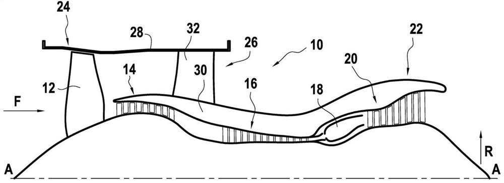
[0056] Figure 1 shows a turbofan engine 10, an example of a turbomachine, in cross-section along a vertical plane passing through its main axis A. Turbofan engine 10 includes fan 12 , low pressure compressor 14 , high pressure compressor 16 , combustor 18 , high pressure turbine 20 and low pressure turbine 22 from upstream to downstream along the cycle of airflow F.

[0057] With respect to the direction of circulation of the air in the turbine, in this case according to the circulation of the air flow F in the turbojet 10 , the terms "upstream" and "downstream" are defined.

[0058]The turbojet engine 10 comprises a fan casing 24 extending rearwardly, that is to say downstream, through an intermediate casing 26 comprising an outer shroud 28 and opposite in radial direction R A parallel inner shroud 30 is arranged inside the outer shroud 28 . The radial direction R is perpendicular to the main axis A.

[0059] The terms "outer" and "inner" are defined with respect to the rad...


PUM


Abstract

The invention relates to a rotor disc (36) for a turbomachine (10), the disc (36) extending circumferentially about an axis (A) and having a plurality of cells (60) configured to receive the roots ofblades (58), each cell (60) having a downstream radial wall (64) configured to axially lock the blade root (58) in the cell (60), each downstream radial wall (64) comprising a ventilation channel (66)for the cell (60) having an inlet orifice (68), which opens into the cell (60), and an outlet orifice (70), which opens onto a downstream surface of the disc (36). The invention also relates to an assembly for a turbomachine, comprising such a disc (36) and an upstream retaining ring, and to a turbomachine comprising such an assembly.

Description

technical field [0001] The invention relates to a rotor disk of a turbomachine, such as a low-pressure turbine rotor disk of a turbojet engine. Background technique [0002] In a known manner, a turbomachine comprises a pneumatic flow path in which a moving impeller (rotor part) recovering energy from the gases produced by the combustion chamber and a distributor (stator part) straightening the air flow in the aerodynamic flow path follow each other. A movable impeller generally consists of a disc moving in rotation about an axis of rotation, which is provided with a plurality of blades. The blades can be manufactured separately and fitted to the disc by interlocking the roots of the blades in the disc cavity. The shape of these cavities is usually obtained by reaming each cavity. Therefore, these cavities are through cavities. These blades are therefore generally axially blocked by retaining rings on their upstream and downstream faces. [0003] In particular, in low-pr...

Claims


Application Information

Patent Timeline
IPC IPC(8): F01D5/08F01D5/30F01D5/32F01D11/00
CPCF01D5/081F01D5/082F01D5/087F01D5/3007F01D5/3015F01D5/32F01D11/006F01D5/30F05D2220/323F05D2240/30F05D2260/201
Inventor 帕特里克·让·劳伦·苏丹娜阿诺·拉桑塔·金利尔
Owner SAFRAN AIRCRAFT ENGINES SAS
Why Eureka
Try Eureka