Converter and submodule of a converter for charging or discharging an energy store

a technology of converters and submodules, which is applied in the direction of electric power, electric vehicles, transportation and packaging, etc., can solve the problems of low conversion efficiency of dc-to-dc converters, and the loss of dc-to-dc converters

Active Publication Date: 2015-03-17
SIEMENS ENERGY GLOBAL GMBH & CO KG
View PDF16 Cites 2 Cited by
  • Summary
  • Abstract
  • Description
  • Claims
  • Application Information

AI Technical Summary

Benefits of technology

[0007]The object of the invention is therefore to provide a submodule and a converter of the type mentioned at the outset which make it possib

Problems solved by technology

Furthermore, the losses of the DC-to-DC converter which ar

Method used


Image

  • Converter and submodule of a converter for charging or discharging an energy store
  • Converter and submodule of a converter for charging or discharging an energy store

Examples


Embodiment Construction

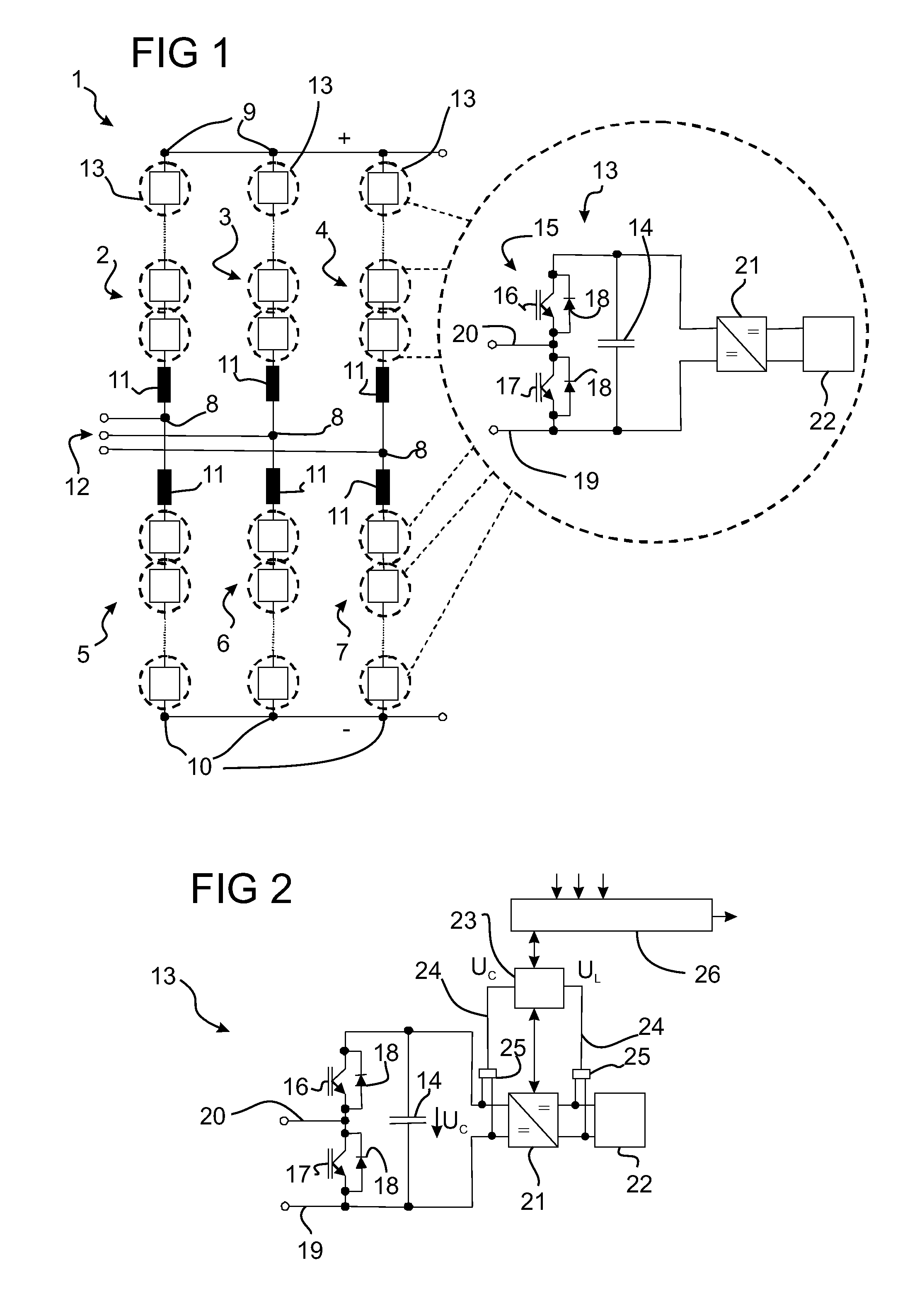
[0021]FIG. 1 shows a schematic of a converter 1, which comprises a bridge circuit of power semiconductor valves 2, 3, 4, 5, 6 and 7, each of said power semiconductor valves extending between an AC voltage connection 8 and a positive DC voltage connection 9 or a negative DC voltage connection 10. Furthermore, each power semiconductor valve 2, 3, 4, 5, 6 and 7 has an inductor 11, which limits the current flow. FIG. 1 only indicates schematically that each AC voltage connection 8 of a converter is connected to the connection of an AC voltage system by a connecting means 12. This conventionally takes place via a transformer or else in DC-coupled fashion with the aid of inductors or coils, which are connected between the AC voltage connections 8 and the AC voltage system (not illustrated in FIG. 1).

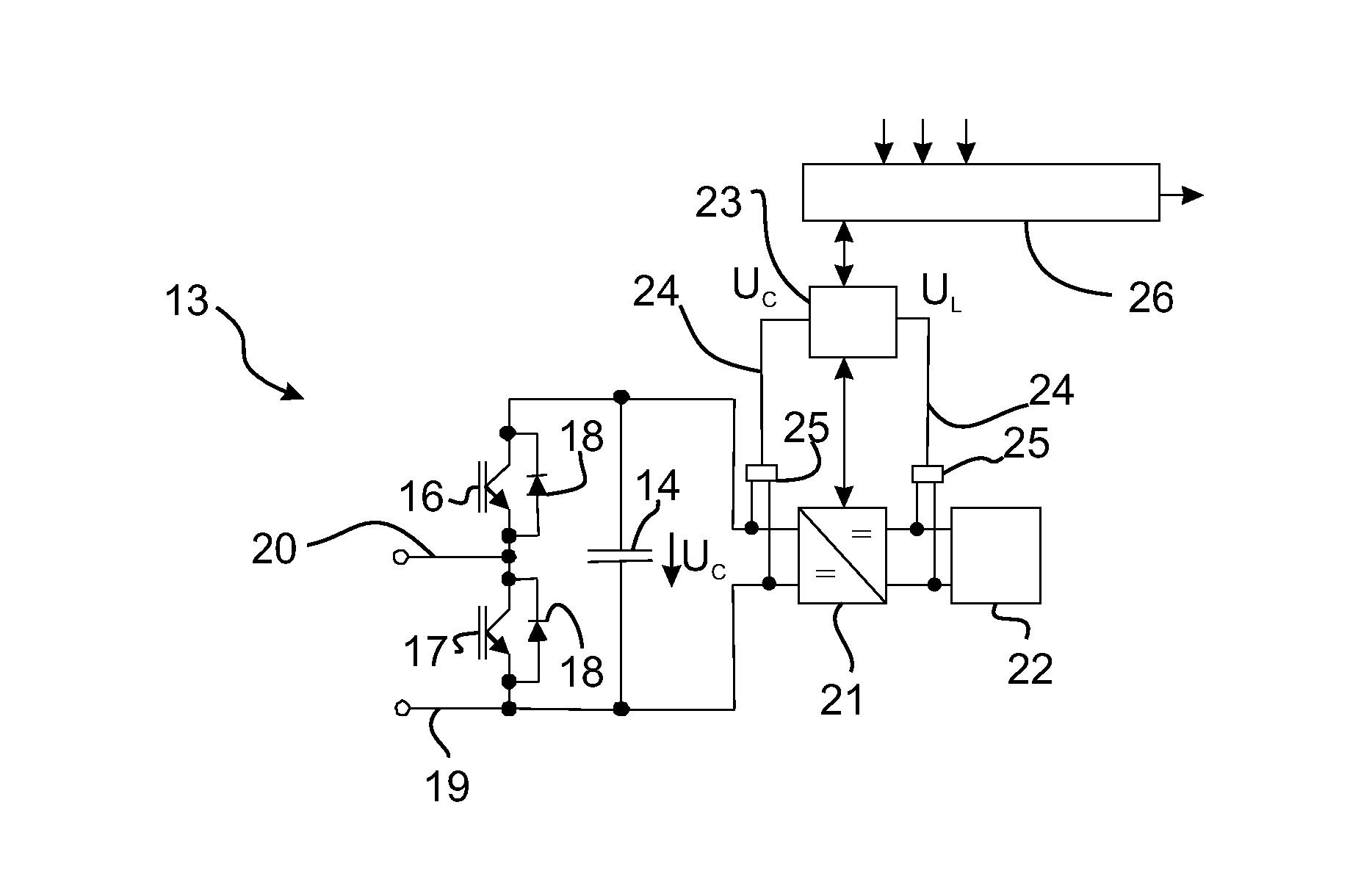
[0022]It is furthermore shown in the figure that each of the power semiconductor valves 2, 3, 4, 5, 6 and 7 has a series circuit comprising bipolar submodules 13, which all have an identical d...


PUM


Abstract

A submodule charges or discharges an energy store and contains a capacitor unit and a power semiconductor circuit having power semiconductors that can be switched on and off. The capacitor unit and the power semiconductor circuit are connected to each other such that, after actuating the power semiconductors, the voltage released at the capacitor unit or a zero voltage can be produced at output terminals of the submodule. In order to provide a submodule allowing individual adaptation of the charging operation to the requirements of the energy store which, is cost-effective, the energy store is connected to the submodule via a DC-DC regulator. The regulator is connected to the capacitor unit and is configured to convert a capacitor voltage into a charge voltage that is required for charging the energy store, and to convert a discharge voltage released at the energy store during discharge into the capacitor voltage.

Description

BACKGROUND OF THE INVENTIONField of the Invention[0001]The invention relates to a submodule for charging or discharging an energy store with a capacitor unit and a power semiconductor circuit, which has power semiconductors which can be switched on and off, the capacitor unit and the power semiconductor circuit being connected to one another in such a way that, depending on the driving of the power semiconductors in the power semiconductor circuit, at least the voltage drop across the capacitor or a zero voltage at output terminals of the submodule can be generated.[0002]The invention furthermore relates to a converter with converter valves, which has a series circuit comprising such submodules.[0003]Such a submodule and such a converter are already known from DE 101 030 31. The converter described therein has converter valves which form a bridge circuit. In this case, each converter valve extends between an AC voltage connection for connecting the converter to an AC voltage system ...

Claims


Application Information

Patent Timeline
IPC IPC(8): H02M7/219H02M7/483
CPCH02M7/483
Inventor LEU, HOLGERRASIC, ANDREJA
Owner SIEMENS ENERGY GLOBAL GMBH & CO KG
Why Eureka
Try Eureka