
Continuous inkjet printing method

inkjet technology, applied in the field of continuous inkjet printing, can solve the problems of acute bursts of 2 non-printing drops in bimodal drop printing modes, effective particle size growth within the recirculating ink supply of a continuous inkjet printing system employing pigmented ink with polymer additive, etc., to achieve high quality drop control, improve print durability, and improve filter life

Inactive Publication Date: 2015-03-31
EASTMAN KODAK CO
View PDF32 Cites 19 Cited by
  • Summary
  • Abstract
  • Description
  • Claims
  • Application Information

AI Technical Summary

Benefits of technology

[0008]The invention provides numerous advantages. It has been found that pigmented inkjet ink compositions comprised of a polymer additive in addition to any polymer dispersant used to disperse the pigment particles, such as structural binder polymers for improved print durability, are subject to degradation during recirculation of the ink in a continuous inkjet printing system employing bimodal drop size generation, impairing drop formation and drop control, and that most surprisingly high quality drop control can be restored by employing an in-line system filter having a smaller particle size removal rating than previously employed in such systems to prevent nozzle plugging. Demanding images can again be printed that are simultaneously substantially free of both DD and PO defects. By careful selection of filter particle removal rating, high filter lifetime and fluid permeability can be achieved while providing adequate control of oversize ink particles formed by a gas deflection continuous inkjet printing system.

Problems solved by technology

It has been found that effective particle size growth within a recirculating ink supply of a continuous inkjet printing system employing a pigmented ink with polymer additive can occur due to ink colloidal instability, or ink drying and incomplete re-dissolution and re-dispersion.
In addition to chronically elevated levels of dark defect within a sound operating window, acute bursts of 2× non-printing drops in bimodal drop printing modes are observed to occur after certain printer operational procedures.

Method used


Image

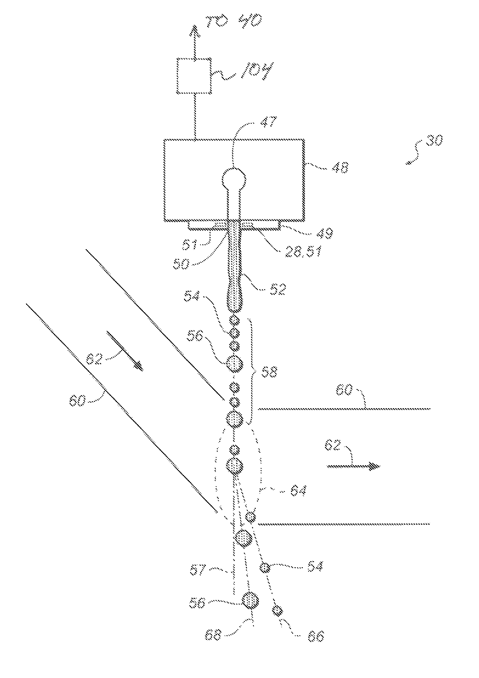
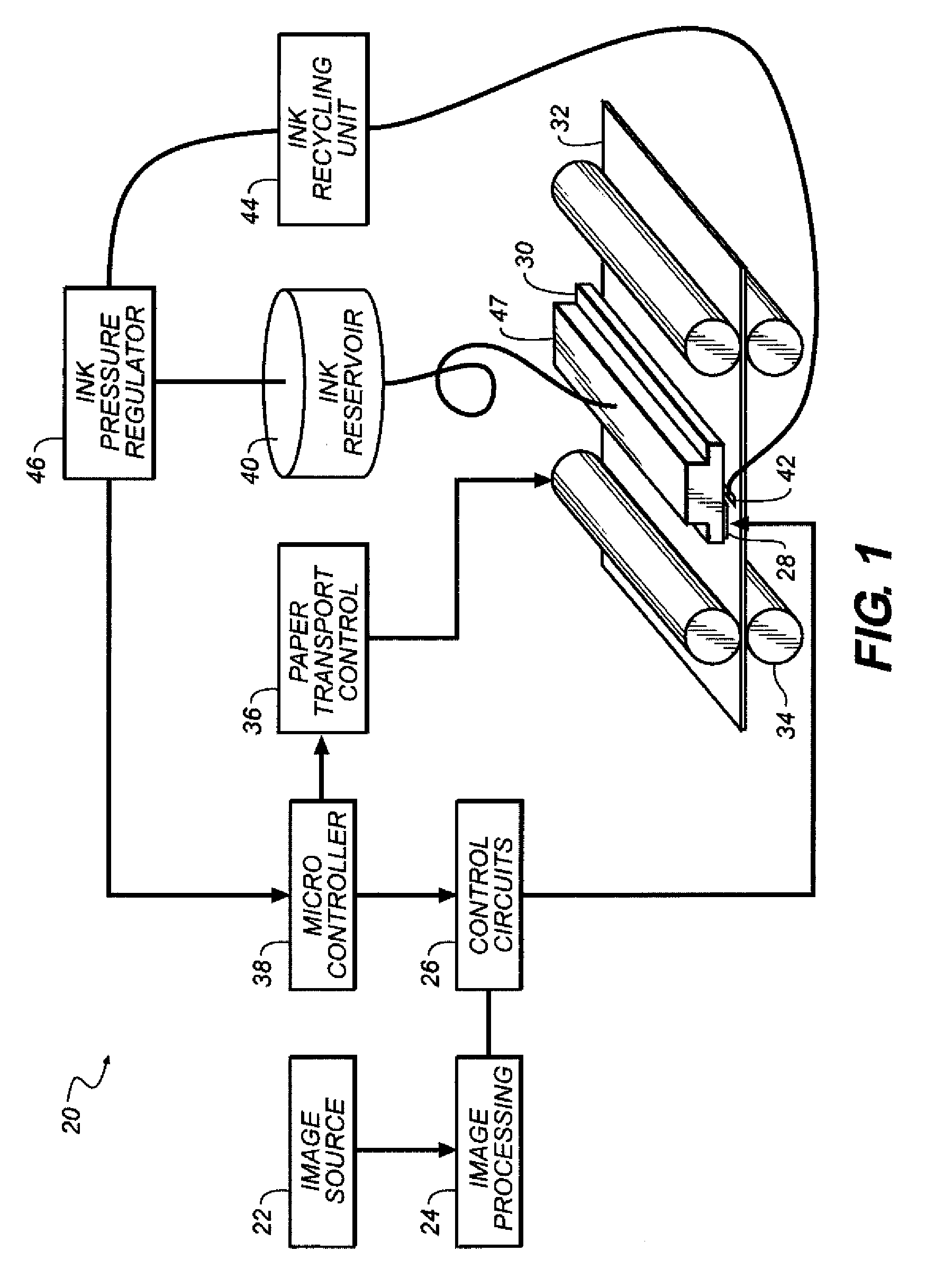
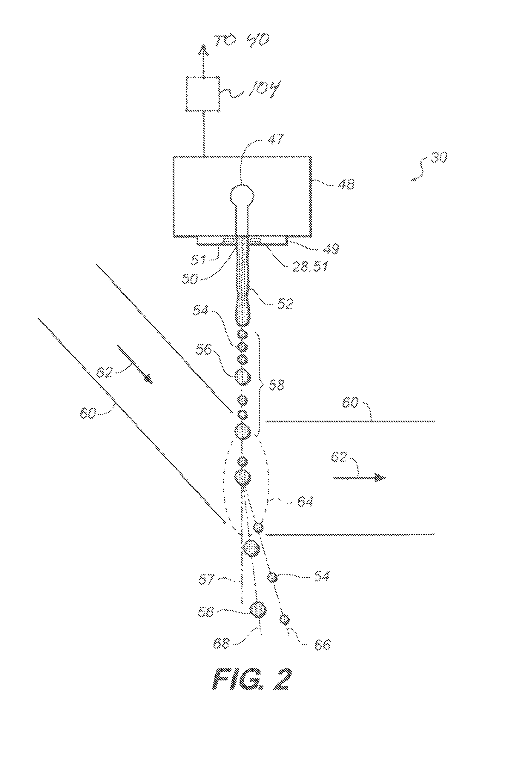
  • Continuous inkjet printing method
  • Continuous inkjet printing method
  • Continuous inkjet printing method

Examples


examples

[0095]The suffix (c) designates control or comparative ink jet ink compositions, while the suffix (e) indicates example ink jet ink compositions. The abbreviation “Wt %” indicates the ingredient weight percent. Carbon black pigment dispersion content is based on the weight percent of carbon black.

Preparation of Continuous Ink Jet Ink Samples

[0096]Polymeric Dispersant and Additive Preparation

[0097]Polymeric Dispersant PD-1

[0098]In a representative procedure, a 5-liter, three-necked round bottom flask equipped with a mechanical stirrer, a reflux condenser, and a gas inlet was charged with 225 g of 1-methoxy-2-propanol and was sparged with nitrogen. Akzo-Nobel Chemicals, Inc., initiator Perkadox AMBN-GR (1.9 g) was added with stirring. A reactant reservoir was charged with 225 g of 1-methoxy-2-propanol, 23.4 g of 1-dodecanethiol, 203.5 g of benzyl methacrylate, 165.0 g of stearyl methacrylate, and 181.5 g of methacrylic acid, and the solution was degassed by nitrogen sparging. AMBN-GR ...


PUM

PropertyMeasurementUnit
particle sizesaaaaaaaaaa
diameteraaaaaaaaaa

Abstract

A method of printing an image with a continuous inkjet printer system employing bimodal drop size generation with pigmented inkjet ink compositions comprising a polymer additive, wherein the liquid ink is an aqueous inkjet ink comprises dispersed pigment colorant particles having a mean particle size of less than 150 nanometers and at least about 0.1 wt % of polymer additive distinct from any polymer dispersant used to disperse the pigment particles, and recirculating liquid ink supplied to the nozzle if the printer system from a liquid ink source is in-line filtered with a filter selected to be effective at retaining particles having particle sizes equal to and greater than 0.6 micrometers from the liquid ink and to pass the dispersed pigment particles. The invention enables high quality drop control in a continuous inkjet printing system.

Description

FIELD OF THE INVENTION[0001]The invention relates generally to the field of inkjet printing methods, and in particular to continuous inkjet printing of aqueous pigmented ink compositions. More specifically, the invention relates to finer filtration of inkjet ink compositions containing a polymer additive during fluid recirculation to provide high speed continuous inkjet printing with reduced drop control defects that lead to print artifacts.BACKGROUND OF THE INVENTION[0002]In one form of binary continuous inkjet (CIJ) printing, such as described in U.S. Pat. Nos. 6,554,410; 6,588,888; 6,863,385; and 6,866,370, a printhead produces fluid drops by thermal stimulation of the fluid jet of inkjet ink using ring heaters surrounding the nozzle orifice that initiate pinch-off of the fluid ligament and its induced reorganization into a spherical drop during flight. Unlike electrostatic deflection CIJ, the drops are not monodisperse, and two populations of relatively large drops and relativel...

Claims


Application Information

Patent Timeline
Patent Type & Authority Patents(United States)
IPC IPC(8): B41J2/07B41J2/175B41J2/02B41J2/09B41J2/03B41J2/105C09D11/10C09D11/322C09D11/324
CPCC09D11/10B41J2/105C09D11/322C09D11/324B41J2002/031
Inventor SOWINSKI, ALLAN FRANCISHASELER, SIMON C.LINK, ROBERTMEHTA, RAJESH VINODRAIGRIFFIN, TODD RUSSELL
Owner EASTMAN KODAK CO
Learn More