
Engine and pod assembly for an aircraft, equipped with an anti-icing device including a source of radiation and pulse control unit connected to the source of radiation

a pod and pod technology, applied in the direction of machines/engines, mechanical equipment, transportation and packaging, etc., can solve the problems of asymmetry of rotation of ice layer and rough off-balance, and achieve the effect of improving the efficiency of anti-icing devices, reducing the consumption of them, and easy integration

Active Publication Date: 2015-04-07
SN DETUDE & DE CONSTR DE MOTEURS DAVIATION S N E C M A +1
View PDF16 Cites 4 Cited by
  • Summary
  • Abstract
  • Description
  • Claims
  • Application Information

AI Technical Summary

Benefits of technology

This solution reduces energy consumption and effectively limits ice growth and detachment, preventing large ice pieces from forming and ensuring efficient anti-icing with reduced structural complexity and power requirements.

Problems solved by technology

The result is an asymmetry of rotation of the ice layer.
This causes a rough off-balance which generates vibrations of the nose cone favouring the detachment of ice.

Method used


Image

  • Engine and pod assembly for an aircraft, equipped with an anti-icing device including a source of radiation and pulse control unit connected to the source of radiation
  • Engine and pod assembly for an aircraft, equipped with an anti-icing device including a source of radiation and pulse control unit connected to the source of radiation

Examples


Embodiment Construction

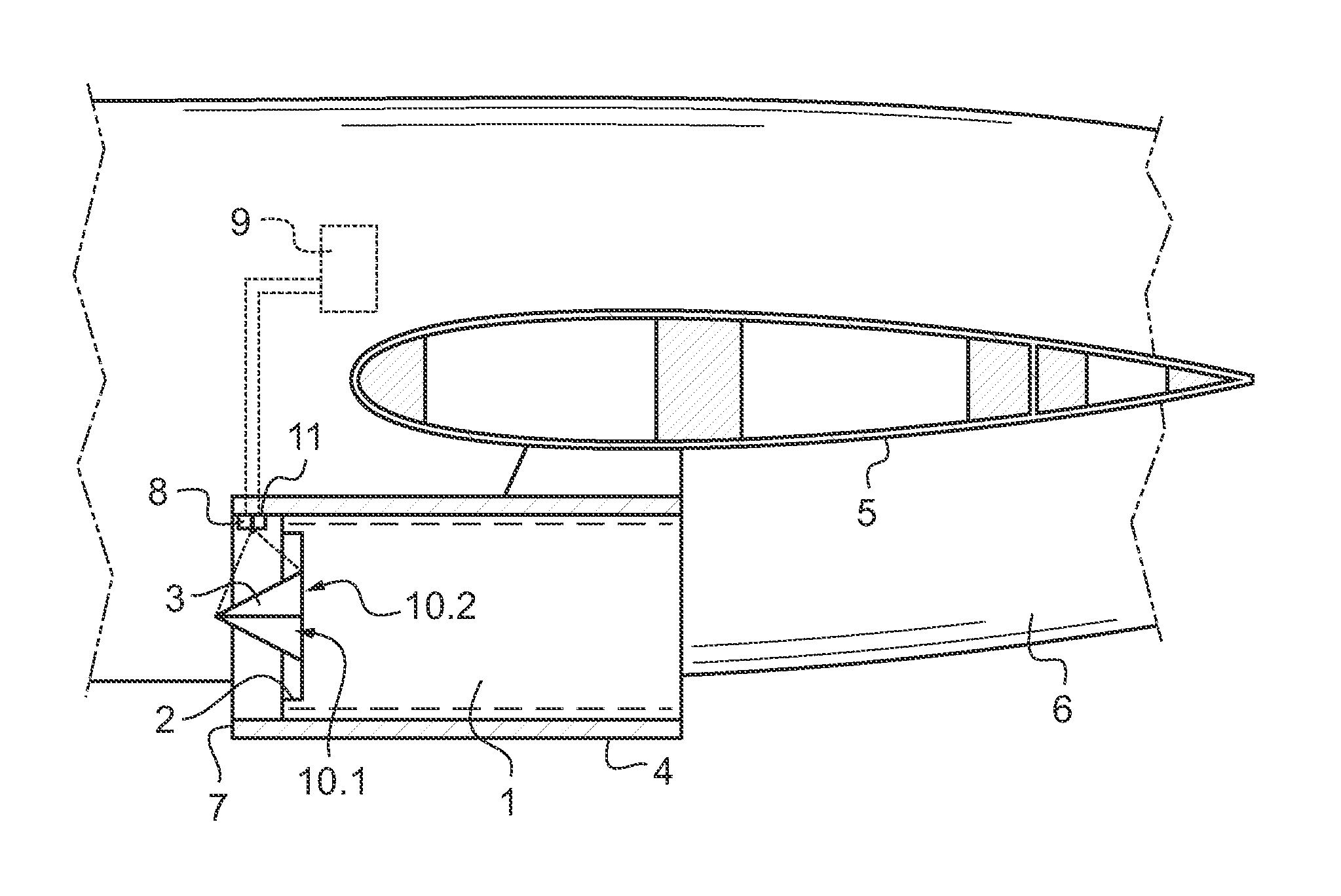
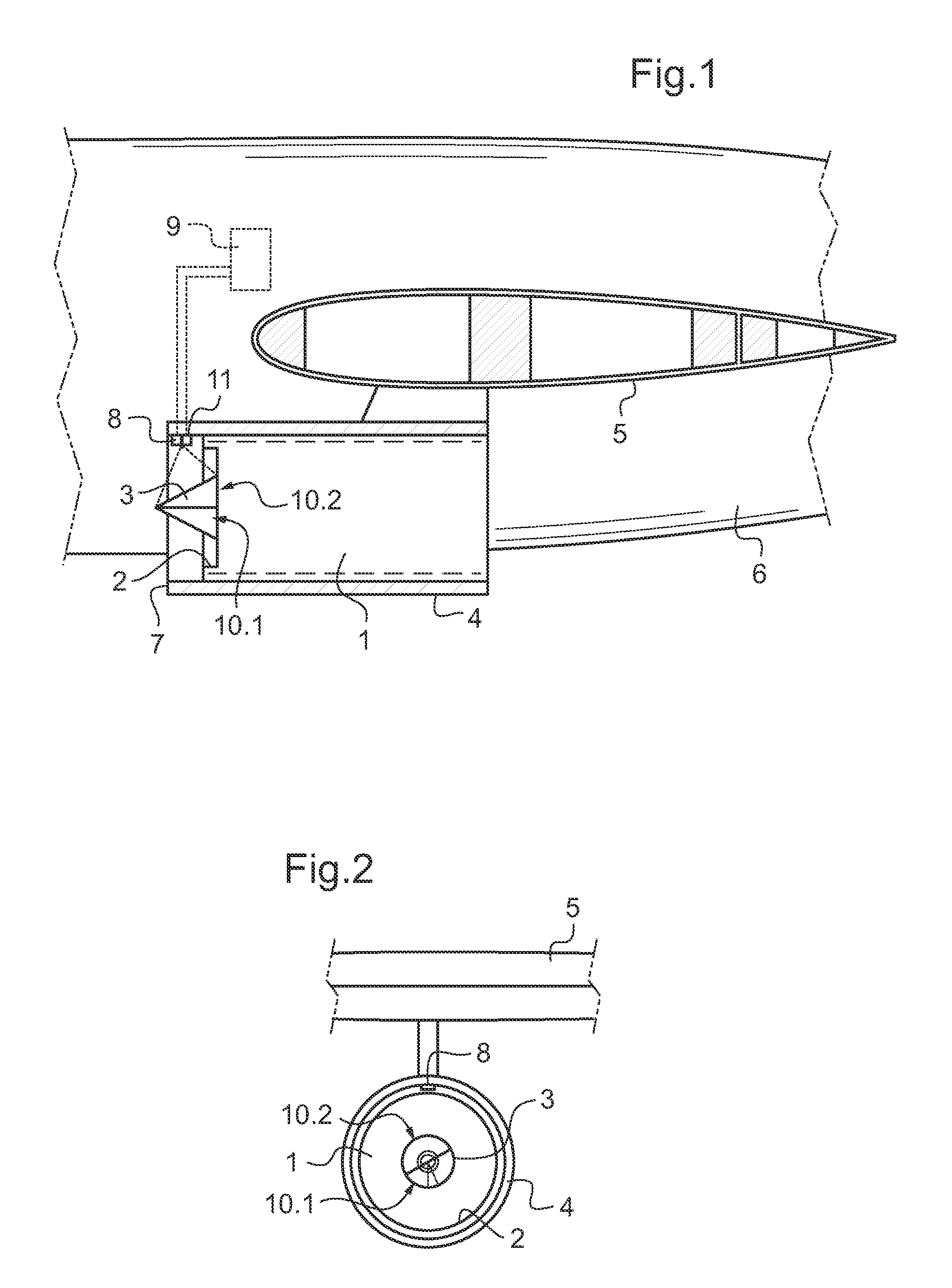
[0031]While referring to the figures, an assembly according to the invention includes an engine of the turbojet type indicated by 1. The engine 1 successively and axially includes an inlet 2, a compressor, a combustion chamber, a turbine and an exhaust nozzle. In the inlet 2 is mounted a nose cone 3 fixed to a shaft driven into rotation by the turbine of the engine 1. The engine 1 is roughly symbolised by a rectangle and will not be described here since the structure thereof is known per se and is not the subject of the present invention.

[0032]The assembly includes a pod 4 receiving the engine 1. The pod 4 is fixed to a wing 5 of said aircraft 6 and includes a leading edge 7 surrounding the inlet opening 2 of the engine 1.

[0033]Finally, the assembly includes a device for limiting the formation of ice on the nose cone 3.

[0034]Here this device includes means associated with the nose cone 3 and means associated in the vicinity of the leading edge 7 of the pod 4.

[0035]In the vicinity of...


PUM


Abstract

An engine and pod assembly for an aircraft includes a pod receiving an engine having an air intake. A rotating nose cone extends on the nose cone, as well as a device for limiting the formation of ice. The device includes means for creating a circumferential heterogeneity of ice on the nose cone.

Description

CROSS-REFERENCE TO RELATED APPLICATIONS[0001]This application is a 371 National Stage of PCT / EP2010 / 053190, filed on Mar. 12, 2010, for which priority is claimed under 35 U.S.C. §119; which claims priority of U.S. Provisional Patent Application No. 61 / 172,467 filed on Apr. 24, 2009 under 35 U.S.C. §119(e), and Application No. 09 01208 filed in France on Mar. 13, 2009 under 35 U.S.C. §119; the entire contents of all of which are hereby incorporated by reference.BACKGROUND OF THE INVENTIONField of the Invention[0002]The present invention relates to an engine and pod assembly for an aircraft. The invention is more particularly adapted to jet engines and other turbojet engines.[0003]An engine for an aircraft of the straight flow turbojet or double fan types includes an air intake, a compressor with several stages, a combustion chamber, a compressor-driving turbine and a jet pipe propelling nozzle. In the air intake, an inlet nose cone extends which is mounted on a shaft driven into rota...

Claims


Application Information

Patent Timeline
Patent Type & Authority Patents(United States)
IPC IPC(8): F02G3/00B64D15/00B64D29/00F02C7/047
CPCB64D15/00B64D29/00F02C7/047
Inventor DUFRESNE DE VIREL, FRANCOISPEALAT, MICHELJOYEZ, PATRICKPONTOIZEAU, BRUCELACUISSE, JEAN-FRANCOISWINTENBERGER, SYLVIE
Owner SN DETUDE & DE CONSTR DE MOTEURS DAVIATION S N E C M A
Learn More