Controller for protectively reducing an output of a converting circuit

a technology of converting circuit and controller, which is applied in the field of controller, can solve the problems of remote control airplane out of control and remote control airplane may crash, and achieve the effect of effective protection

Inactive Publication Date: 2015-04-14
GREEN SOLUTION TECH CO LTD
View PDF19 Cites 4 Cited by
  • Summary
  • Abstract
  • Description
  • Claims
  • Application Information

AI Technical Summary

Benefits of technology

[0007]In view of the latching protection of the conventional controller that is not suitable for those need to continuously supply power, the present invention uses “soft-protection mechanism”, which provides an effective protection for system and the power management Integrated Circuit as well as protects the system from damage. At the same time, due to the soft-protection mechanism, the system has enough response time for retrieving to normal operation.

Problems solved by technology

However, the controller immediately stops operation in some specific application environment, such as a remote control airplane, which would result in that the remote control airplane is out of control.
The remote control airplane may crash if the controller cannot recover the power supplying system in a short time.

Method used


Image

  • Controller for protectively reducing an output of a converting circuit
  • Controller for protectively reducing an output of a converting circuit
  • Controller for protectively reducing an output of a converting circuit

Examples


first embodiment

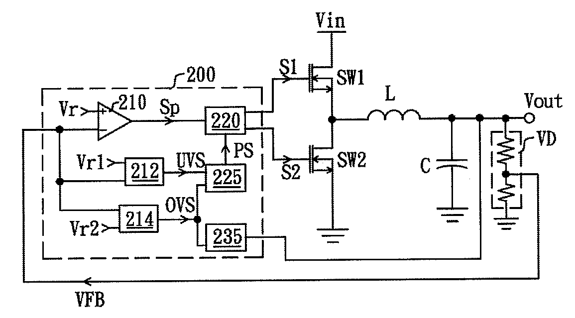
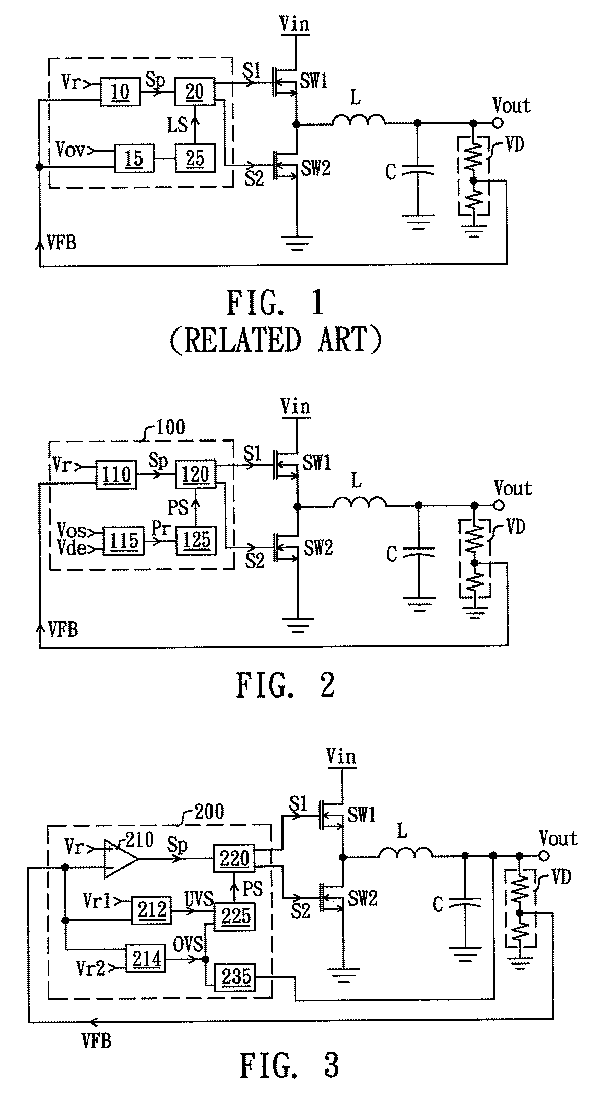
[0022]FIG. 3 is a schematic diagram of a DC-DC buck converter according to the present invention. The DC-DC buck converter comprises a controller 200 and a converting circuit, configured to provide an output voltage Vout to a load (not shown). The controller 200 comprises an error amplifier 210, an under-state judgment circuit 212, an over-state judgment circuit 214, a logic control circuit 220, a protection control circuit 225 and an energy discharging circuit 235. The converting circuit comprises a high-side transistor switch SW1, a low-side transistor switch SW2, an inductance L and an output capacitance C. The high-side transistor switch SW1 and the low-side transistor switch SW2 are connected in series. One end of the high-side transistor switch SW1 is coupled to an input voltage Vin, the other end thereof is coupled to one terminal of the inductance L and one end of the low-side transistor switch SW2. The other end of the low-side transistor switch SW2 is grounded. The other t...

second embodiment

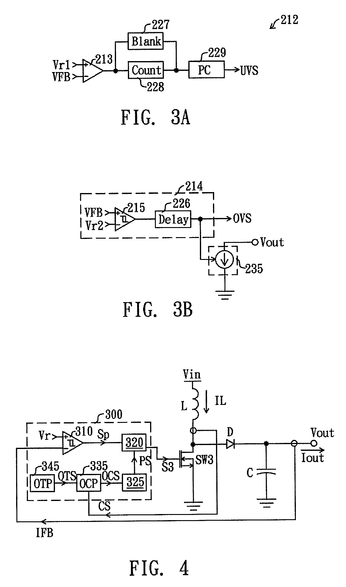
[0026]FIG. 4 is a schematic diagram of a DC-DC boost converter according to the present invention. The DC-DC boost converter comprises a controller 300 and a converting circuit, configured to provide an output current Iout to a load (not shown). The controller 300 comprises a ripple control circuit 310, an over-current judgment circuit 335, an over-temperature judgment circuit 345, a logic control circuit 320 and a protection control circuit 325. The converting circuit comprises a transistor switch SW3, an inductance L, a diode D and an output capacitance C. The inductance L and the transistor switch SW3 are connected in series. One terminal of the inductance L is coupled to an input voltage Vin, the other terminal thereof is coupled to a positive end of the diode D and one end of the transistor switch SW3. The other end of the transistor switch SW3 is grounded. A negative end of the diode D is coupled to the output capacitance C for providing an output current Iout. An input end of...


PUM


Abstract

A controller for protectively reducing an output of a converting circuit includes a feedback circuit, a logic control circuit, an over-state judgment circuit, and a protection control circuit, is disclosed. The feedback circuit generates a modulation signal according to an output of a converting circuit. The logic control circuit is coupled to the feedback circuit and controls the converting circuit according to the modulation signal for stabilizing the output of the converting circuit. The over-state judgment circuit receives an over-state reference signal and a detecting signal, and generates a protection signal in response to levels of the detecting signal and the over-state reference signal. The protection control circuit is coupled to the logic control circuit and the over-state judgment circuit and controls the logic control circuit to lower the output of the converting circuit when receiving the protection signal.

Description

BACKGROUND OF THE INVENTION[0001](1) Field of the Invention[0002]The present invention relates to a controller, and more particularly relates to a controller for protectively reducing an output of a converting circuit.[0003](2) Description of the Prior Art[0004]The conventional power management Integrated Circuits (ICs) immediately stop operating and execute a latching protection for avoiding damage to the integrated circuits and systems and further ensuring the safety and reliability of integrated circuits when judging that the system operates abnormally to trigger a corresponding protection mechanism, such as over-temperature protection, over-voltage protection, under-voltage protection, over-current protection and so on.[0005]FIG. 1 is a schematic diagram of a conventional DC-DC buck converter. The DC-DC buck converter comprises a controller and a converting circuit. The controller comprises a feedback circuit 10, an over-voltage judgment circuit 15, a logic control circuit 20 an...

Claims


Application Information

Patent Timeline
Patent Type & Authority Patents(United States)
IPC IPC(8): G05F1/565G05F1/595
CPCG05F1/595H02M1/32H02M3/156
Inventor LEE, LI-MINYU, CHUNG-CHESHIU, SHIAN-SUNGGAN, QUAN
Owner GREEN SOLUTION TECH CO LTD
Why Eureka
Try Eureka