
Polishing pad and manufacturing method therefor

a polishing pad and manufacturing method technology, applied in the field of polishing pads, can solve the problems of unsatisfactory dry polishing pads the above-described dry polishing pads are still hard, and the dry polishing pads are still unsatisfactory in terms of reducing the number of scratches (scratches) formed on the surface of workpieces, so as to achieve less scratches (

Active Publication Date: 2015-04-21
FUJIBO HLDG
View PDF41 Cites 2 Cited by
  • Summary
  • Abstract
  • Description
  • Claims
  • Application Information

AI Technical Summary

Benefits of technology

[0038]Since the polishing pad of the present invention has a low Young's modulus E, the strong pressing to a workpiece is suppressed, and scars (scratches) are less likely to be formed. In addition, because of the high porosity (low density), scars due to clogging are also less likely to be formed. Moreover, since the polishing pad of the present invention is softer than polishing pads having polishing layers molded by conventional dry methods, the polishing pad of the present invention is excellent also in polishing rate and polishing uniformity. Meanwhile, since the polishing pad of the present invention is dry-molded, the polishing pad has a lower wearing rate of the polishing surface and undergoes less change in cell diameters in the depth direction than wet-molded polishing pads. Hence, the polishing pad of the present invention can retain a constant polishing state for a long period. Therefore, although dry-molded, the polishing pad of the present invention can be advantageously used for both primary processing and finish processing.BRIEF EXPLANATION OF DRAWINGS
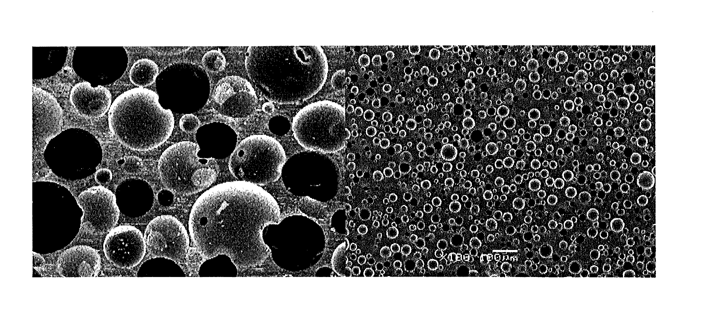
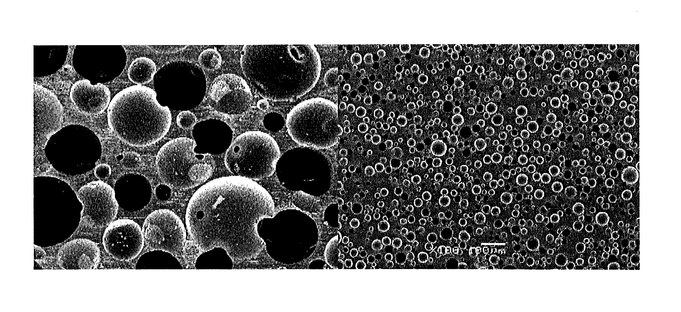
[0039]FIG. 1 shows a cross-sectional view (left) of a polishing pad showing an embodiment of the present invention and a cross-sectional view (right) of a polishing pad (Comparative

Problems solved by technology

However, the above-described dry polishing pads are still hard, and tend to apply a pressure to a workpiece in a localized manner.
Hence, the dry polishing pads are unsatisfactory in terms of reduction of polishing scars (scratches) formed on the surface of a workpiece.
In addition, the dry polishing pads still have a problem of high possibility of clogging.
On the other hand, a polishing pad having a soft polishing layer molded by a wet method has a low hardness, has large openings of a suede type, and has a non-uniform foam structure.
Hence, the polishing pad having a soft polishing layer cannot retain a polishing state at a certain level for a long period.

Method used


Image

  • Polishing pad and manufacturing method therefor
  • Polishing pad and manufacturing method therefor

Examples


example 1

[0145]In Example 1, as a first component, which was a prepolymer, an isocyanate group-containing urethane prepolymer having an isocyanate content of 7.8% and an NCO equivalent weight of 540 was used. The prepolymer was obtained by reacting 2,4-TDI (286 parts) and the PTMG (714 parts) having a number average molecular weight of approximately 1000. This prepolymer was heated to 55° C., and degassed under reduced pressure. As a second component, which was a chain extender, solid MOCA was used. The solid MOCA was melt at 120° C., and degassed under reduced pressure. A third component, an aqueous dispersion, was obtained by mixing the three-functional PPG (42 parts) having a number average molecular weight of 3000, water (3 parts), a catalyst (TOYOCAT-ET manufactured by Tosoh Corporation) (1 part), a silicone-based surfactant (SH-193 manufactured by Dow Corning Corporation) (1 part) with each other at 35° C. for 1 hour with stirring. Then, the aqueous dispersion was degassed under reduce...

example 5

[0149]In Example 5, as a first component, which was a prepolymer, an isocyanate group-containing urethane prepolymer having an isocyanate content of 7.8% and an NCO equivalent weight of 540 was used. The prepolymer was obtained by reacting 2,4-TDI (286 parts) and the PTMG (714 parts) having a number average molecular weight of approximately 1000. This prepolymer was heated to 55° C., and degassed under reduced pressure. As a second component, which was a chain extender, the liquid MOCA (234 parts) was degassed under reduced pressure. A third component, an aqueous dispersion, was obtained by mixing the three-functional PPG (41 parts) having a number average molecular weight of 3000, water (3 parts), a catalyst (TOYOCAT-ET manufactured by Tosoh Corporation) (1 part), and a silicone-based surfactant (SH-193 manufactured by Dow Corning Corporation) (4 parts) with each other with stirring. Then, the aqueous dispersion was degassed under reduced pressure. The first component, the second c...

example 10

[0153]In Example 10, as a first component, which was a prepolymer, an isocyanate group-containing urethane prepolymer having an isocyanate content of 10.0% and an NCO equivalent weight of 420 was used. The prepolymer was obtained by reacting 2,4-TDI (325 parts) and the PTMG (675 parts) having a number average molecular weight of approximately 1000. This prepolymer was heated to 55° C., and degassed under reduced pressure. As a second component, which was a chain extender, the liquid MOCA (397 parts) was degassed under reduced pressure. A third component, an aqueous dispersion, was obtained by mixing the three-functional PPG (43 parts) having a number average molecular weight of 3000, water (1 part), a catalyst (TOYOCAT-ET manufactured by Tosoh Corporation) (1 part), and a silicone-based surfactant (SH-193 manufactured by Dow Corning Corporation) (4 parts) with each other with stirring. Then, the aqueous dispersion was degassed under reduced pressure. The first component, the second ...


PUM

PropertyMeasurementUnit
Young's modulusaaaaaaaaaa
frequencyaaaaaaaaaa
storage elastic modulusaaaaaaaaaa

Abstract

Provided are a polishing pad which remedies the problem of scratches occurring when a conventional hard (dry) polishing pad is used, which is excellent in polishing rate and polishing uniformity, and which can be used for not only primary polishing but also finish polishing, and a manufacturing method therefor. The polishing pad is a polishing pad for polishing a semiconductor device, comprising a polishing layer having a polyurethane-polyurea resin foam containing substantially spherical cells, wherein the polyurethane-polyurea resin foam has a Young's modulus E in a range from 450 to 30000 kPa, and a density D in a range from 0.30 to 0.60 g / cm3.

Description

TECHNICAL FIELD[0001]The present invention relates to a polishing pad, and more specifically to a CMP polishing pad for a semiconductor device.BACKGROUND ART[0002]Since surfaces of materials such as silicon, hard disks, mother glass for liquid crystal displays, and semiconductor devices need to be flat, the surfaces are polished by the loose abrasive method using a polishing pad. The loose abrasive method is a method in which the work surface of a workpiece is polished while a slurry (polishing liquid) containing abrasive grains is supplied between a polishing pad and the workpiece.[0003]In a polishing pad for a semiconductor device, the surface of the polishing pad is required to have openings for retaining abrasive grains, rigidity for keeping the flatness of the surface of the semiconductor device, and elasticity for preventing scratches on the surface of the semiconductor device. As a polishing pad meeting these requirements, a polishing pad having a polishing layer manufactured...

Claims


Application Information

Patent Timeline
Patent Type & Authority Patents(United States)
IPC IPC(8): B24D11/00H01L21/304B24B37/22B24B37/24C08G18/10C08G18/48C08G101/00C08J9/12
CPCH01L21/304C08J9/12C08G18/4854C08G18/10B24B37/22B24B37/24C08G18/3814C08G18/48C08J2375/04C08G2101/0008C08G2101/0083C08J2207/00C08G2110/0066C08G2110/0083C08G18/4829C08G2110/0008B24D3/26C08G18/00C08G18/65
Inventor ITOYAMA, KOUKIMIYAZAWA, FUMIO
Owner FUJIBO HLDG
Learn More