Organic electroluminescent apparatus

a technology of electroluminescent apparatus and organic material, applied in the direction of discharge tube luminescnet screen, discharge tube/lamp details, electric discharge lamps, etc., can solve the problems of moisture and oxygen likely to penetrate the device, the coating edge is not waterproof and oxygen resistant, and the water resistance and oxygen resistance are not good. to achieve the effect of improving water resistance and oxygen resistan

Active Publication Date: 2015-04-21
AU OPTRONICS CORP
View PDF16 Cites 9 Cited by
  • Summary
  • Abstract
  • Description
  • Claims
  • Application Information

AI Technical Summary

Benefits of technology

[0008]The invention provides an organic electroluminescent apparatus having an extending path where moisture and oxygen enter an organic light-emitting device layer to improve water-resistance and oxygen-resistance.
[0011]Based on the above, in the organic electroluminescent apparatus of the invention, the patterned structure layer is disposed in the non-light-emitting region, so that the encapsulation film on the patterned structure layer has a concave-convex surface. In addition, in the organic electroluminescent apparatus of the invention, the aggregated enhanced layer is disposed in the non-light-emitting region, so that the organic layer and the second inorganic layer on the aggregated enhanced layer have concave-convex surfaces. When moisture and oxygen enter the encapsulation film or the organic layer in the non-light-emitting region, the concave-convex structures extend a path where moisture and oxygen enter the organic light-emitting device layer, such that the water-resistance and the oxygen-resistance of the organic electroluminescent apparatus is improved.

Problems solved by technology

If external moisture and oxygen enter the organic electroluminescent apparatus, an electro-chemical reaction between the moisture and the oxygen and the organic light-emitting device layer occurs, such that electrodes and organic light-emitting materials inside the organic light-emitting device layer are damaged and dark dots are generated on the light-emitting region so as to influence the performance of the organic electroluminescent apparatus.
In addition, the cover cannot be applied to a flexible organic electroluminescent apparatus.
The coating process causes problems such as shadow effects occurring at a film edge in the non-light-emitting region and a poor patterned covering, which cause a coating edge to have poor water-resistance and oxygen-resistance.
Therefore, moisture and oxygen are likely to penetrate the device through the coating edge in the non-light-emitting region to damage the organic electroluminescent apparatus.

Method used


Image

  • Organic electroluminescent apparatus
  • Organic electroluminescent apparatus
  • Organic electroluminescent apparatus

Examples


first embodiment

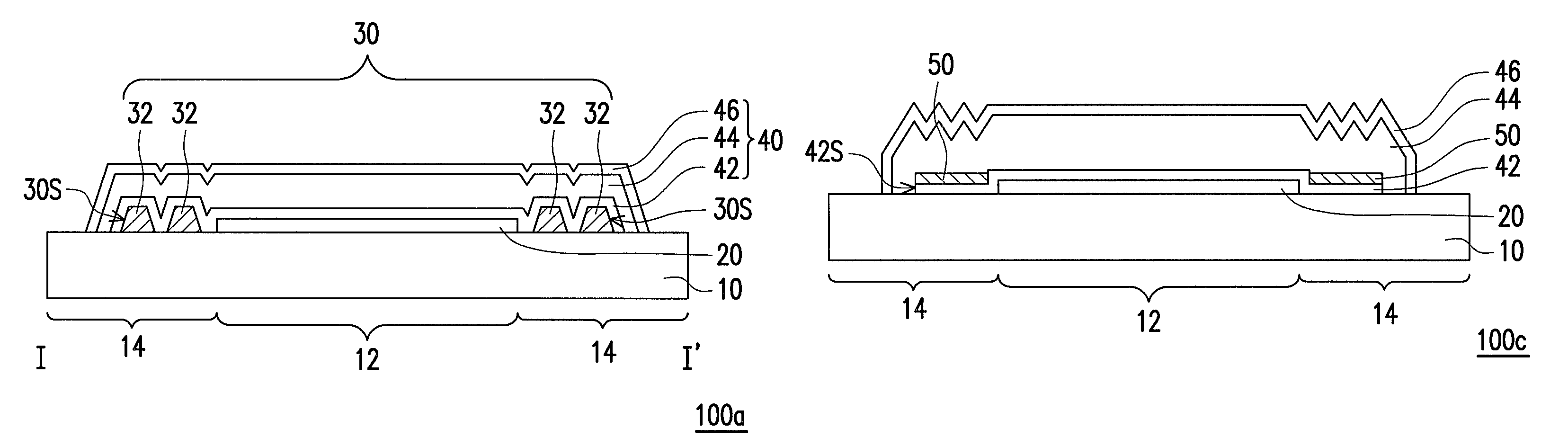
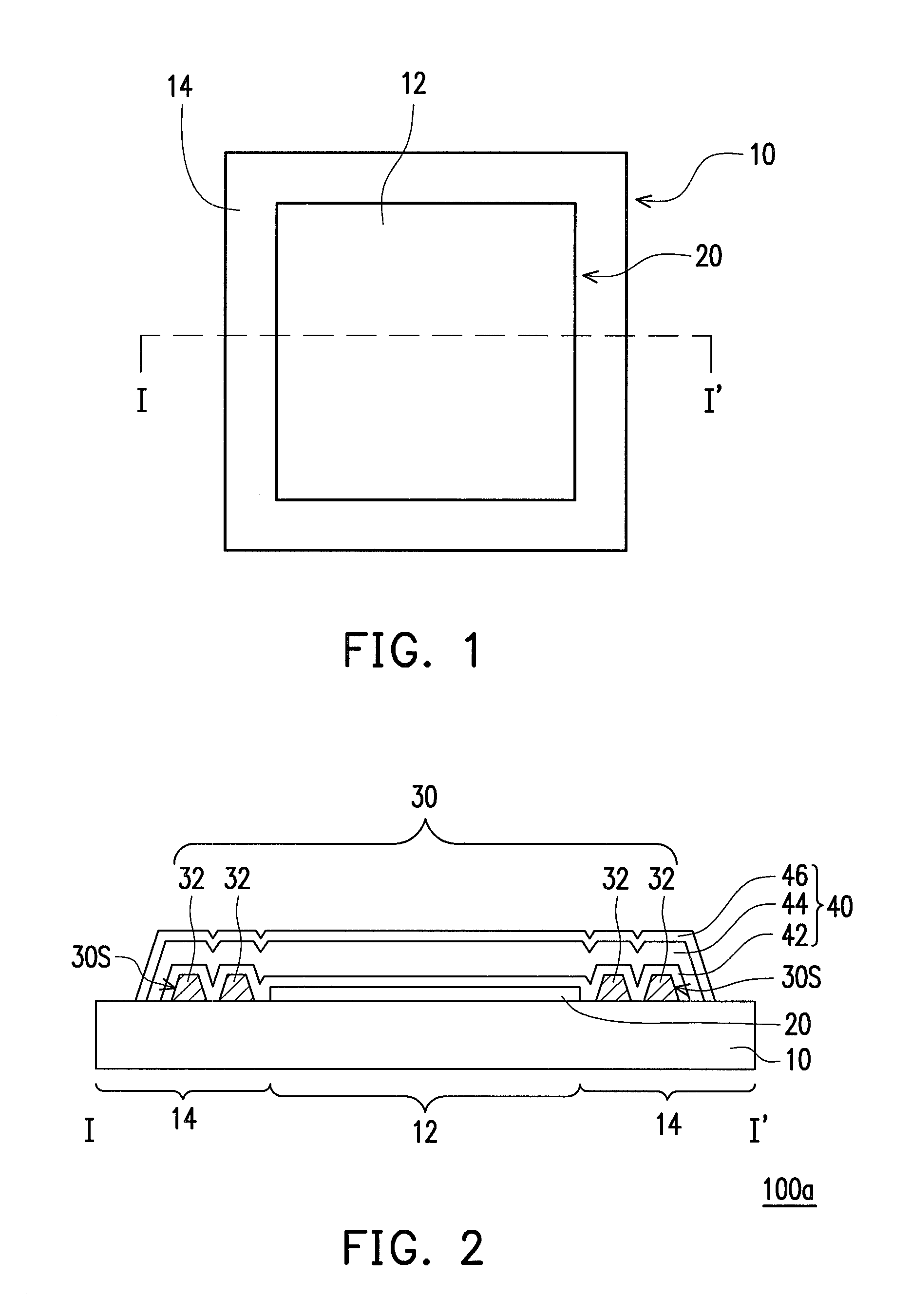
[0019]FIG. 1 is a schematic top view of an organic electroluminescent apparatus according to the first embodiment of the invention. FIG. 2 is a schematic cross-sectional view taken along a sectional line I-I′ depicted in FIG. 1. It should be noted that, to clearly illustrate a structure of an organic electroluminescent apparatus 100a, FIG. 1 illustrates a substrate 10 and an organic light-emitting device layer 20 and omits other components.

[0020]Please refer to both FIGS. 1 and 2. The organic electroluminescent apparatus 100a includes a substrate 10, an organic light-emitting device layer 20, a patterned structure layer 30 and an encapsulation film 40. The substrate 10 has a light-emitting region 12 and a non-light-emitting region 14, wherein the non-light-emitting region 14 surrounds the light-emitting region 12.

[0021]The organic light-emitting device layer 20 is disposed on the substrate 10 and located in the light-emitting region 12. In general, the organic light-emitting device ...

second embodiment

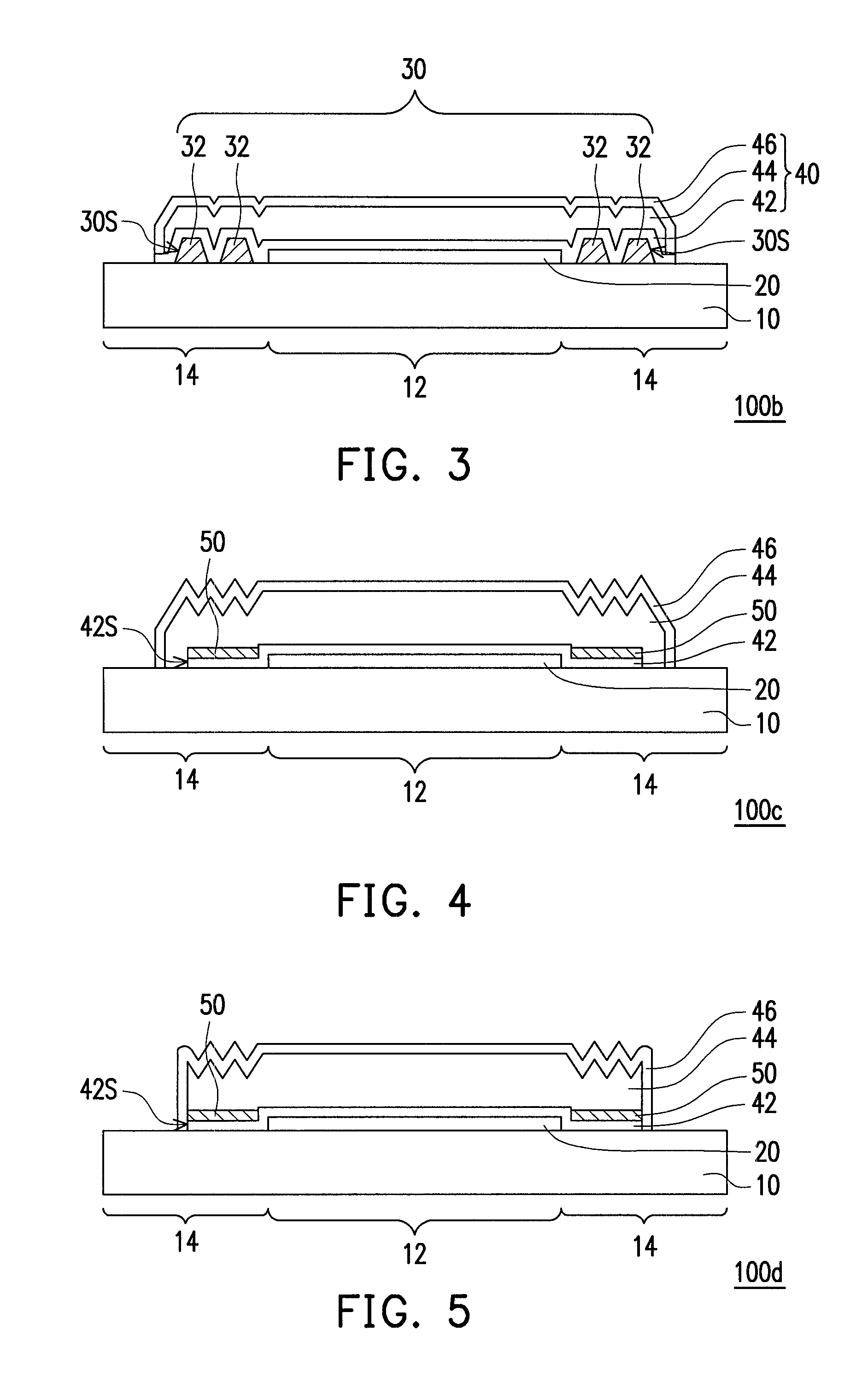
[0029]FIG. 3 is schematic cross-sectional view of an organic electroluminescent apparatus according to the second embodiment of the invention. Please refer to FIG. 3. The present embodiment is similar to the embodiment shown in FIG. 2. Therefore, identical elements are indicated with identical reference numbers, and descriptions thereof are not repeated herein. An organic electroluminescent apparatus 100b includes a substrate 10, an organic light-emitting device layer 20, a patterned structure layer 30, and an encapsulation film 40. The substrate 10 has a light-emitting region 12 and a non-light-emitting region 14, wherein the non-light-emitting region 14 surrounds the light-emitting region 12.

[0030]The organic light-emitting device layer 20 is disposed on the substrate 10 and located in the light-emitting region 12. The patterned structure layer 30 is disposed on the substrate 10 and located in the non-light-emitting region 14. The encapsulation film 40 is disposed on the substrate...

third embodiment

[0035]FIG. 4 is a schematic cross-sectional view of an organic electroluminescent apparatus according to the third embodiment of the invention. Please refer to FIG. 4. An organic electroluminescent apparatus 100c includes a substrate 10, an organic light-emitting device layer 20, a first inorganic layer 42, an aggregated enhanced layer 50, an organic layer 44, and a second inorganic layer 46. The substrate 10 has a light-emitting region 12 and a non-light-emitting region 14, wherein the non-light-emitting region 14 surrounds the light-emitting region 12.

[0036]The organic light-emitting device layer 20 is disposed on the substrate 10 and located in the light-emitting region 12. In general, the organic light-emitting device layer 20 may include a first electrode, a second electrode, and organic light-emitting materials disposed between the first electrode and the second electrode. The organic light-emitting materials may include a red organic light-emitting material, a green organic l...


PUM


Abstract

An organic electroluminescent apparatus including a substrate, an organic light-emitting device layer, a patterned structure layer and an encapsulation film is provided. The substrate has a light-emitting region and a non-light-emitting region. The organic light-emitting device layer is disposed on the substrate in the light-emitting region. The patterned structure layer is disposed on the substrate in the non-light-emitting region. The encapsulation film is disposed on the substrate and covers the organic light-emitting device layer and the patterned structure layer. A surface of the encapsulation film on the patterned structure layer is a concave-convex surface, and a surface of the encapsulation film on the organic light-emitting device layer is an even surface.

Description

CROSS-REFERENCE TO RELATED APPLICATION[0001]This application claims the priority benefit of Taiwan application serial no. 101107033, filed on Mar. 2, 2012. The entirety of the above-mentioned patent application is hereby incorporated by reference herein and made a part of this specification.BACKGROUND OF THE INVENTION[0002]1. Field of the Invention[0003]The invention relates to a light-emitting apparatus, particularly to an organic electroluminescent apparatus.[0004]2. Description of Related Art[0005]An organic electroluminescent apparatus is a self-emissive display. Organic electroluminescent apparatuses have properties such as wide view angles, high response speed (about more than one hundred times faster than the response speed of liquid crystals), light weight, the ability to be miniaturized as required by hardware equipment, high light-emitting efficiency, high color rendering index, and planar light source. Therefore, organic electroluminescent apparatuses have great potential...

Claims


Application Information

Patent Timeline
Patent Type & Authority Patents(United States)
IPC IPC(8): H01J1/62H01J63/04H01L51/52
CPCH01L51/5256H10K50/8445
Inventor WANG, CHUN-JANCHANG, CHIA-HAOYANG, CHIH-JENCHANG, CHUAN-HSIU
Owner AU OPTRONICS CORP
Why Eureka
Try Eureka