Low sidelobe reflector antenna with shield

a reflector antenna and shield technology, applied in the direction of antennas, waveguide horns, radiating element housings, etc., can solve the problems of increasing manufacturing, installation and ongoing maintenance costs, overall size and complexity, and increasing overall manufacturing costs

Active Publication Date: 2015-04-28
COMMSCOPE TECH LLC
View PDF33 Cites 183 Cited by
  • Summary
  • Abstract
  • Description
  • Claims
  • Application Information

AI Technical Summary

Benefits of technology

[0048]A dielectric radiator portion 25 situated between the waveguide transition portion 5 and a sub-reflector support portion 30 of the dielectric block 10 is also increased in size. The dielectric radiator portion 25 may be dimensioned, for example, with a minimum diameter of at least ⅗ of the sub-reflector diameter. The enlarged dielectric radiator portion 25 is operative to pull signal energy outward from the end of the waveguide 3, thus minimizing the diffraction at this area observed in conventional dielectric cone sub-reflector configurations, for example as shown in FIG. 4. The conventional dielectric cone has an outer diameter of 28 mm and a minimum diameter in a “radiator region” of 11.2 mm, which at a desired operating frequency in the 22.4 Ghz microwave band corresponds to corresponding to 2.09 and 0.84 wavelengths, respectively.
[0066]From the foregoing, it will be apparent that the present invention may bring to the art a reflector antenna with improved electrical performance and / or significant manufacturing cost efficiencies. Because the front feed self-supported sub-reflector assembly reflector antenna has an axisymmetric antenna structure, the cost and complexity of the dual offset reflector antenna structure may be entirely avoided. The reflector antenna according to the invention may be strong, lightweight and may be repeatedly cost efficiently manufactured with a very high level of precision.

Problems solved by technology

These additional structure and / or path alignment tuning requirements significantly increase the overall size and complexity of the resulting antenna assembly, thereby increasing the manufacturing, installation and ongoing maintenance costs.
Further, the plurality of angled features and / or steps in the dielectric block requires complex manufacturing procedures which increase the overall manufacturing cost.
Therefore, although common in the non-deep dish reflector antennas, conventional deep dish reflector antenna configurations such as U.S. Pat. No. 6,919,855 typically do not utilize a separate forward projecting cylindrical shield.

Method used


Image

  • Low sidelobe reflector antenna with shield
  • Low sidelobe reflector antenna with shield
  • Low sidelobe reflector antenna with shield

Examples


Embodiment Construction

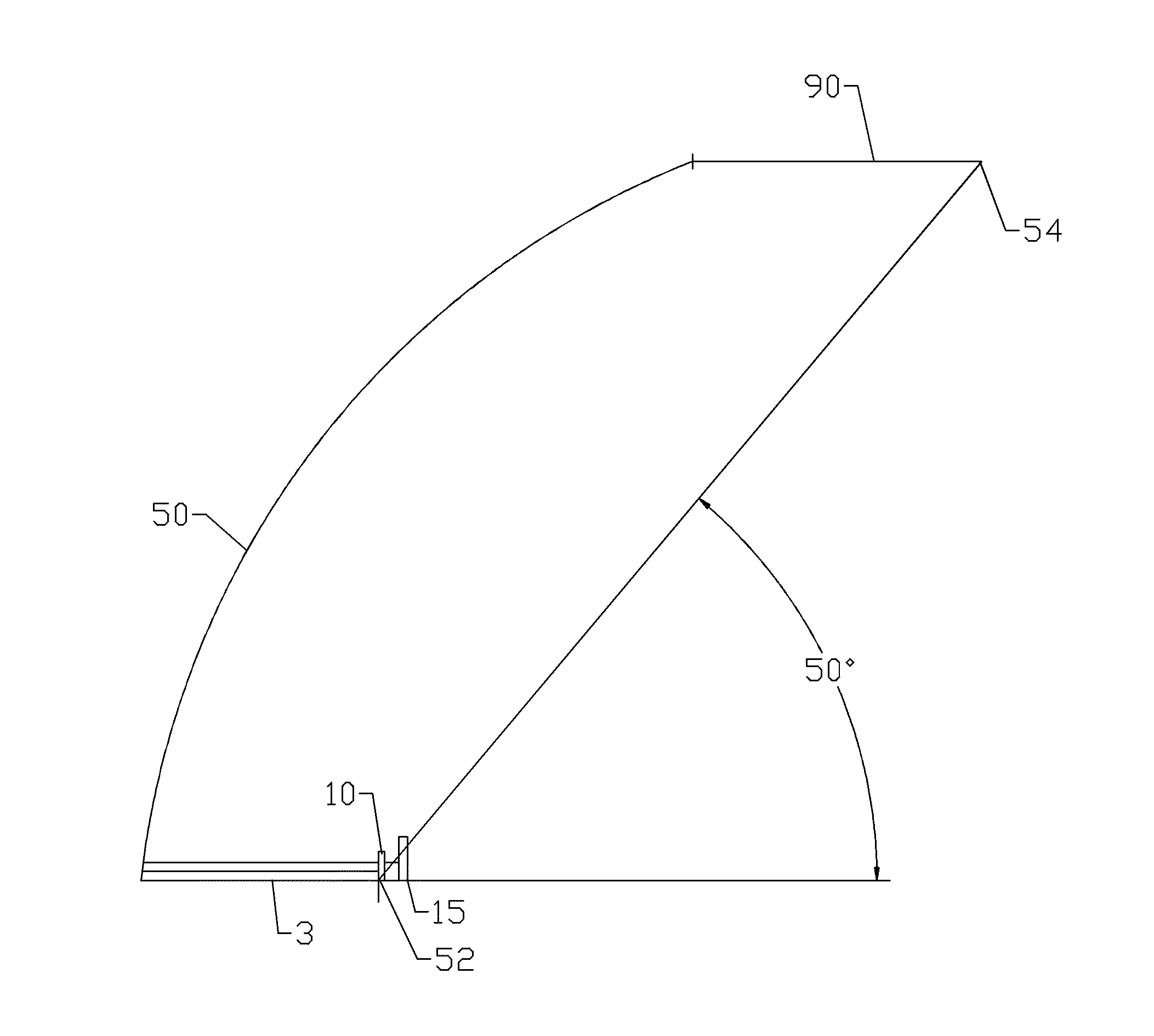
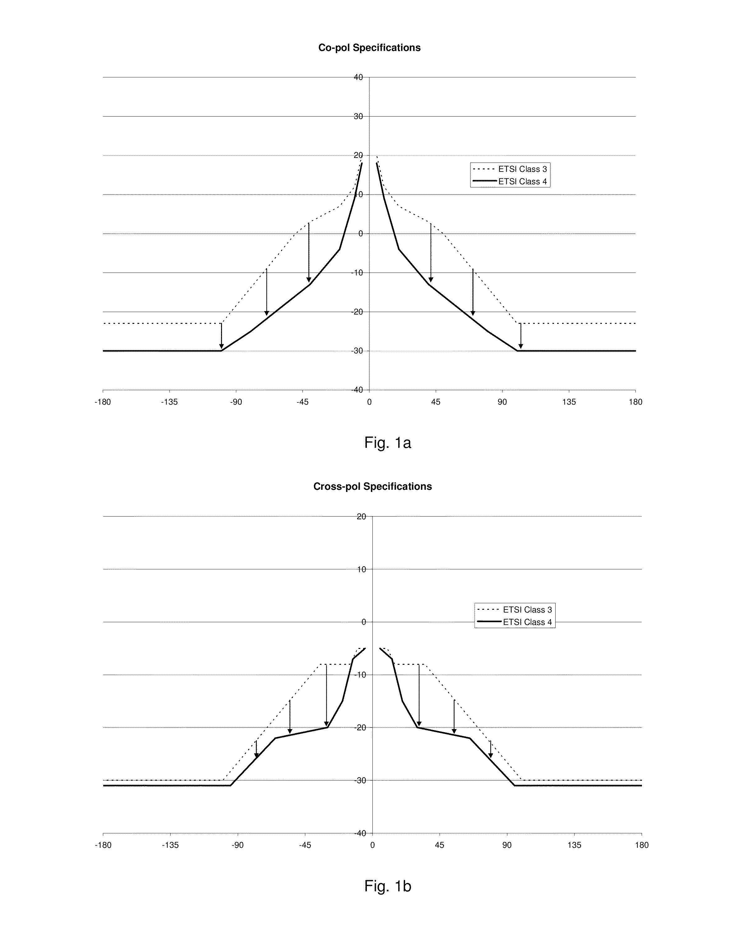
[0046]The inventors have recognized that improvements in primary radiation pattern control obtained from dielectric cone sub-reflector assemblies dimensioned to concentrate signal energy upon a mid-wall area of reflector dish, paired with improved shielding at the reflector dish periphery, can enable a cost effective self-supported sub-reflector front feed type reflector antenna to meet extremely narrow radiation pattern envelope electrical performance specifications, such as the ETSI Class 4 RPE.

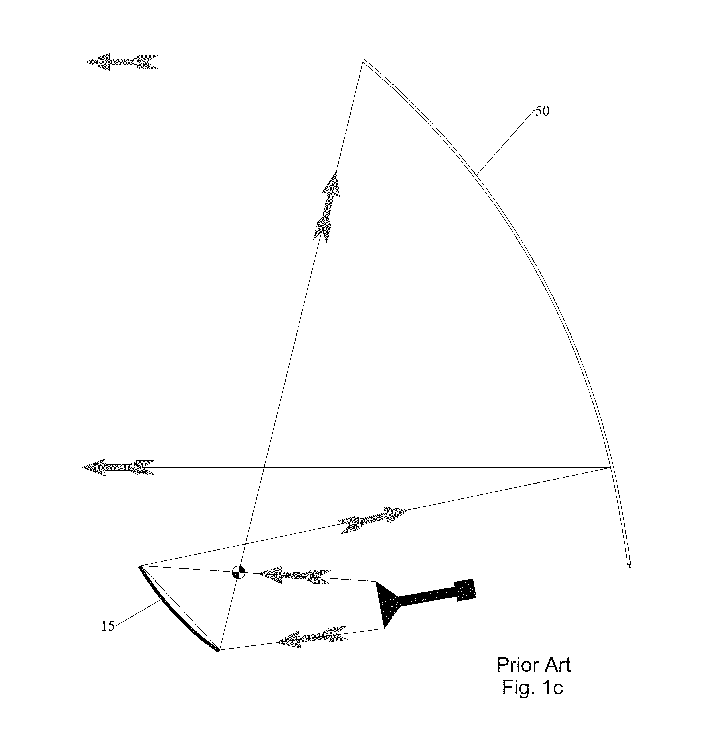
[0047]As shown in FIGS. 2a, 2b and 3, a cone radiator sub-reflector assembly 1 is configured to couple with the end of a feed boom waveguide 3 at a waveguide transition portion 5 of a unitary dielectric block 10 which supports a sub-reflector 15 at the distal end 20. The sub-reflector assembly 1 utilizes an enlarged sub-reflector diameter for reduction of sub-reflector spill-over. The sub-reflector 15 may be dimensioned, for example, with a diameter that is 2.5 wavelengths or more of a desi...


PUM

PropertyMeasurementUnit
subtended angleaaaaaaaaaa
angleaaaaaaaaaa

Abstract

A front feed reflector antenna with a dish reflector has a wave guide is coupled to a proximal end of the dish reflector, projecting into the dish reflector along a longitudinal axis. A dielectric block may be coupled to a distal end of the waveguide and a sub-reflector coupled to a distal end of the dielectric block. A shield is coupled to the periphery of the dish reflector. A subtended angle between the longitudinal axis and a line between the focal point and a distal periphery of the shield is 50 degrees or less.

Description

CROSS REFERENCE TO RELATED APPLICATIONS[0001]This application is a continuation-in-part of commonly owned co-pending U.S. Utility patent application Ser. No. 13 / 229,829, titled “Low Sidelobe Reflector Antenna”, filed Sep. 12, 2011 by Stephen Simms, Ronald J. Brandau, Junaid Syed and Douglas Cole, currently pending and hereby incorporated by reference in its entirety.BACKGROUND[0002]1. Field of the Invention[0003]This invention relates to a microwave dual reflector antenna. More particularly, the invention provides a low cost, self-supported front feed reflector antenna with a low sidelobe signal radiation pattern characteristic configurable for the reflector antenna to satisfy rigorous radiation pattern envelope standards, such as the European Telecommunications Standards Institute (ETSI) Class 4 radiation pattern envelope.[0004]2. Description of Related Art[0005]Front feed dual reflector antennas direct a signal incident on the main reflector onto a sub-reflector mounted adjacent t...

Claims


Application Information

Patent Timeline
Patent Type & Authority Patents(United States)
IPC IPC(8): H01Q19/18H01Q1/42H01Q13/02H01Q15/16H01Q17/00H01Q19/19
CPCH01Q15/16H01Q13/02H01Q19/193H01Q1/42H01Q13/0266H01Q17/001Y10T29/49016H01Q19/026H01Q19/022
Inventor BRANDAU, RONALD JSYED, JUNAID
Owner COMMSCOPE TECH LLC
Why Eureka
Try Eureka