Systems and methods for glass manufacturing

a glass and glass technology, applied in the field of combustion furnaces, can solve the problems of molten glass forming tendency to foam, rapid melting of glass batches, and high turbulen

Active Publication Date: 2015-05-05
JOHNS MANVILLE CORP
View PDF304 Cites 36 Cited by
  • Summary
  • Abstract
  • Description
  • Claims
  • Application Information

AI Technical Summary

Problems solved by technology

The introduction of high flow rates of oxidant and fuel into the molten glass, and the expansion of the gases cause rapid melting of the glass batch and much turbulence.
However, one drawback to submerged combustion is the tendency of the molten glass to foam.
The foam layer may impede the ability to apply heat to the glass using combustion burners, and may also impede the rate at which further bubbles in the melt rise and thus effect expulsion of the bubbles and mass flow rate of the melt in the channels.
In extreme cases, the foam generated may interfere with the traditional energy application methods employed, which may cause systems to require shutdown, maintenance and may result in a process upset.
Attempts to reduce the foam problem through process adjustments have not met with complete success in reducing foam to an acceptable amount.

Method used


Image

  • Systems and methods for glass manufacturing
  • Systems and methods for glass manufacturing
  • Systems and methods for glass manufacturing

Examples


embodiment 400

[0077]FIG. 4 is a schematic cross-sectional view of another auxiliary burner embodiment 400 including a ceramic burner block useful in certain embodiments of systems and methods of the present disclosure. Embodiment 400 includes an oxidant conduit 14 connecting to an oxidant plenum 20. Oxidant plenum 20 routes oxidant between the OD of fuel conduit 12 and an inner surface 22 of a cavity in a ceramic burner block 4. Burner block 4 includes a hot end 6 having an exit 8 for combustion products, and includes an internal surface having a straight portion 26 and a tapered portion 28, where tapered portion 28 forms a combustion chamber 34. Straight portion 26 forms a chamber 35 (FIG. 5) in which is positioned tapered nozzle section 16 of fuel conduit 12.

[0078]FIG. 5 is a schematic diagram of a portion of the burner of FIG. 4, illustrating certain dimensions of auxiliary burner embodiment 400. Length Ls is the length of chamber 35 defined by straight section 26 of inner surface 22 of the ce...

embodiment 600

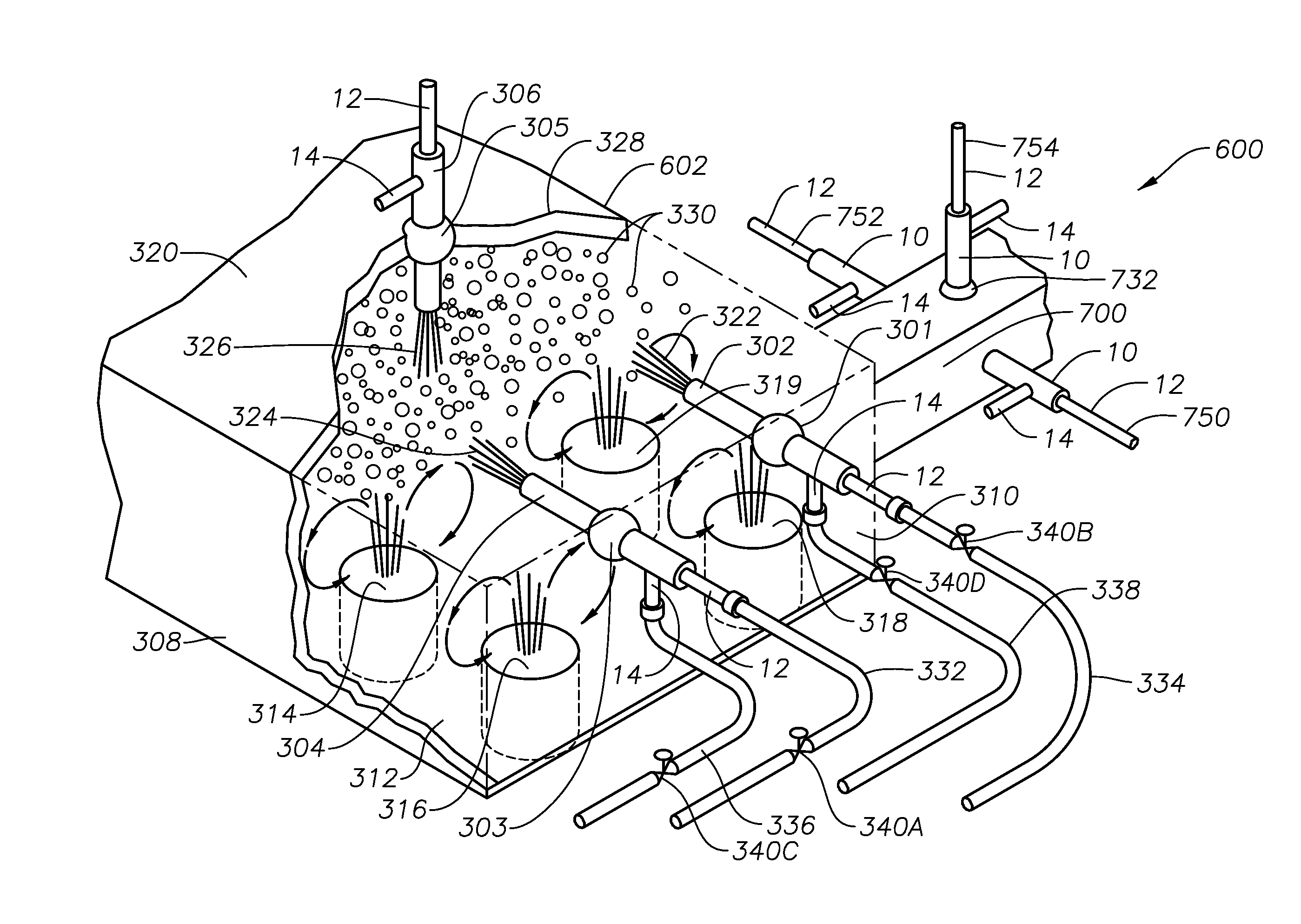
[0080]Roof 320 is illustrated schematically as having a cut-out portion 328, making it possible to view the internals of SC melter 602. In accordance with embodiments of the present disclosure, flame and / or combustion products 322, 324 from sidewall-mounted auxiliary wall burners 302, 304, and flame and / or combustion products 326 from roof-mounted auxiliary burner 306 are shown impinging on and either bursting some of the bubbles in a layer of bubbles 330, and / or heating the bubble layer sufficiently to burst at least some of the bubbles. The film forming the outside surfaces of the bubbles, formed as they are from liquefied glass-forming materials, then flows back into the bulk of the molten material. It should be noted that embodiment 600 is merely illustrative, and that certain embodiments may have only one auxiliary burner, for example only auxiliary burner 302, or only auxiliary burner 306.

[0081]Also illustrated in FIG. 6 are fuel supply conduits 332, 334, and oxidant supply co...

embodiment 700

[0084]Auxiliary burners 750 and 752 are mounted in burner blocks 712 with the forward end 726 of each burner extending into an aperture 728 in each burner block 712. Quick disconnects (not illustrated in FIG. 7) for oxidant and fuel streams may be provided for each burner 750, 752 and positioned outside its respective burner block 712 to enable the fuel lines and oxidant lines to be attached thereto. Bubbles 730 remaining in molten glass may rise in the molten glass and help to produce or maintain a foam layer 719, or foam layer 719 might be in part left over from the SC melter 602 (FIG. 6). In any case, in embodiment 700 auxiliary burners 750, 752 serve to push foam layer 719 toward projections 718, and may provide flame that extends into side channels 722, 724 to heat the outer portions of the molten glass stream. Roof-mounted auxiliary burner 754 is illustrated schematically as mounted via an adjustable mount 732, such as a ceramic-lined ball turret, in roof 708, and causes its c...


PUM

PropertyMeasurementUnit
velocityaaaaaaaaaa
velocityaaaaaaaaaa
diameteraaaaaaaaaa

Abstract

Submerged combustion systems and methods of use to produce glass. One system includes a submerged combustion melter having a roof, a floor, a wall structure connecting the roof and floor, and an outlet, the melter producing an initial foamy molten glass. One or more non-submerged auxiliary burners are positioned in the roof and / or wall structure and configured to deliver combustion products to impact at least a portion of the bubbles with sufficient force and / or heat to burst at least some of the bubbles and form a reduced foam molten glass.

Description

CROSS-REFERENCE TO RELATED APPLICATIONS[0001]This application is related to assignee's U.S. non-provisional patent application Ser. No. 12 / 817,754, filed Jun. 17, 2010; Ser. No. 12 / 888,970, filed Sep. 23, 2010; and Ser. Nos. 13 / 267,990; 13 / 268,028; 13 / 268,065; and 13 / 268,098, all filed Oct. 7, 2011, all of which are incorporated herein by reference.BACKGROUND INFORMATION[0002]1. Technical Field[0003]The present disclosure relates generally to the field of combustion furnaces and methods of use to produce glass, and more specifically to systems and methods for reducing foam or its impact during manufacture of glass using submerged combustion melters.[0004]2. Background Art[0005]Submerged combustion melting (SCM) involves melting glass batch materials to produce molten glass by passing oxygen, oxygen-air mixtures or air along with a liquid, gaseous fuel, or particulate fuel in the glass batch, directly into a molten pool of glass usually through burners submerged in a glass melt pool....

Claims


Application Information

Patent Timeline
Patent Type & Authority Patents(United States)
IPC IPC(8): C03B5/235C03B5/20C03B7/06F23C5/08F23D14/22F23D14/32
CPCC03B5/2353C03B5/2356C03B7/06C03B5/202F23C5/08F23D14/22F23D14/32Y02E20/344F27B14/14Y02P40/50Y02E20/34C03B5/20C03B5/2257C03B5/235
Inventor CHARBONNEAU, MARK WILLIAMHUBER, AARON MORGANSHOCK, JEFFREY M.BORDERS, HARLEY ALLEN
Owner JOHNS MANVILLE CORP
Why Eureka
Try Eureka