Microfabricated resonant fluid density and viscosity sensor

Active Publication Date: 2015-05-26
PACE MARIA ESTHER +1
View PDF18 Cites 19 Cited by
  • Summary
  • Abstract
  • Description
  • Claims
  • Application Information

AI Technical Summary

Benefits of technology

[0021]In order to overcome the above-discussed disadvantages of conventional fluidic sensors, one aspect of the present invention utilizes the fact that different resonant frequencies, mode shapes, and geometries of resonators respond differently to a fluid's density and viscosity. A further aspect is that a thin plate in resonance can act a

Problems solved by technology

As disclosed, this sensor is not readily amenable to microfabrication.
The detection duration is a tradeoff between computing complexity and measurement accuracy.
If a sensor is used in a feedback loop, a sensor delay on the order of 1 second would provide unacceptable control if the gain of the feedback loop is high, for instance in a process gas controller.
As the sensor disclosed is not easily adaptable to microfabrication, the cost of adding sensor elements in an array is nearly linear with the number of sensor elements.
The decay method for determining Q is not well suited for low values of Q (ie: high viscosity).
A further limitation in U.S. Pat. No. 7,874,199B2 is that the embodiments rendered therein are not readily adapted to microfabrication.
It will be obvious to those skilled in the art of

Method used


Image

  • Microfabricated resonant fluid density and viscosity sensor
  • Microfabricated resonant fluid density and viscosity sensor
  • Microfabricated resonant fluid density and viscosity sensor

Examples


Embodiment Construction

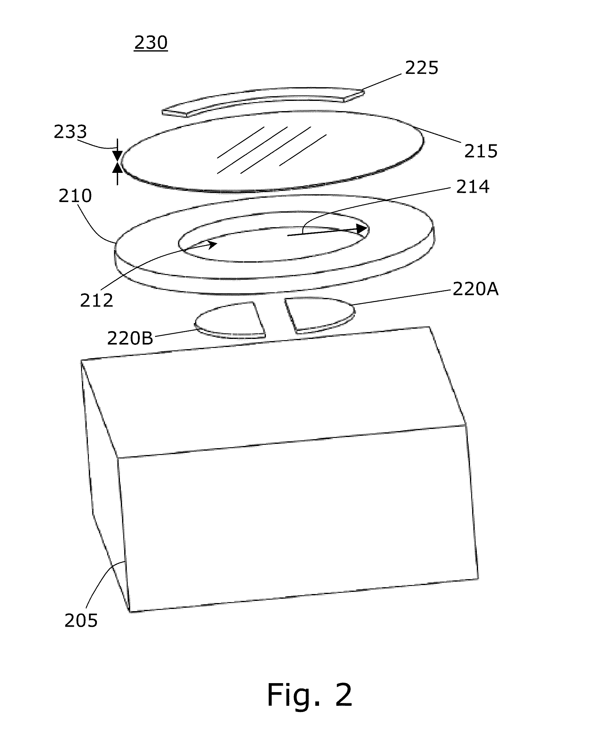
[0071]One aspect of the present invention is a microfabricated resonant sensor, operated at a resonant frequency, which may be variable. A perspective view of the preferred embodiment is shown in FIG. 1. A substrate 105, which may contain drive electronics and detection electronics, having a substantially flat top or principal surface is provided. A support 110 is placed onto principal surface of substrate 105. A thin plate 115, which may behave as a plate with substantial bending stiffness, or as a membrane having substantial in-plane elastic strain, or a combination of these is positioned onto support 110 to form a suspended resonant structure that is free to oscillate in a direction normal to the plane of thin plate 115. A top electrode 125 is formed in electrical contact with thin plate 115.

[0072]A fluid 130 under test, which generally surrounds the sensor is exposed to, and is in communication with thin plate 115.

[0073]An exploded perspective view of the preferred embodiment is...


PUM


Abstract

Determination of fluid properties is important in a variety of research and industrial applications. Real-time measurements in operating fluidic systems are performed for monitoring, diagnosis, and feedback-control. A simplified, microfabricated resonant sensor for separate density and viscosity measurements of a fluid with a common sensor is disclosed. The sensor is micron-scale, so as to produce a minimum of perturbation to the fluid under test, and may be arrayed to probe viscosity and density across a flowstream or vessel. Measurement is performed at resonance peaks, and geometry or operating conditions of sensor are varied to produce different resonance responses useful for separate sensing of density and viscosity of a fluid. Another embodiment includes a method for reducing quiescent in-plate elastic strain in a plate or membrane so as to allow bending-stiffness dominated behavior of a resonator.

Description

[0001]This application claims the benefit of U.S. Provisional Application No. 61 / 570,301, filed Dec. 14, 2011.FIELD OF THE INVENTION[0002]The field of the present invention relates generally to fluidic sensors. In particular, the field of the invention relates to microfabricated and nanofabricated resonant fluid sensors.BACKGROUND[0003]In any application where fluids are used, sensors are often employed to measure properties of the fluid, such applications including aviation, fluid delivery, heat exchange / refrigeration, semiconductor processing, fluid identification and detection, medical and bio-diagnostics. Quantities measured include temperature, viscosity, density, pressure, flow rate, molecular composition and state of matter. Sensors are transducers, which convert the property being measured into another useful form, often electrical, for recording, observing and controlling. In order to make a useful sensor, the device must respond to a physical input change by producing an o...

Claims


Application Information

Patent Timeline
IPC IPC(8): G01N29/00G01H13/00G01N9/00G01N11/10G01N29/036
CPCG01H13/00G01N11/10G01N9/002G01N29/036G01N11/16G01N29/022G01N2291/02818G01N2291/0426
Inventor PACE, MARIA ESTHERPEROZZIELLO, ERIC ANTHONY
Owner PACE MARIA ESTHER
Why Eureka
Try Eureka