Medical device with means to improve transmission of torque along a rotational drive shaft

a technology of rotational drive shaft and transmission shaft, which is applied in the direction of heating, radiation therapy, surgical instruments for heating, etc., can solve the problems of reducing the flexibility of the shaft, reducing the efficiency of the shaft, and reducing the number of fiber bundles. the effect of resolution

Active Publication Date: 2015-05-26
SUNNYBROOK HEALTH SCI CENT
View PDF19 Cites 13 Cited by
  • Summary
  • Abstract
  • Description
  • Claims
  • Application Information

AI Technical Summary

Benefits of technology

[0025]The present invention provides means for minimizing undesired artifacts, such as non-uniform rotational distortion, in the rotational velocity near the distal end of a minimally invasive medical device. Such devices would include an imaging probe which undergoes rotational movement to scan surrounding tissue in bodily lumens and cavities.
[0026]Embodiments of the present invention provide means for minimizing the effect of non-uniform rotational distortion that occurs in imaging systems that use an elongate rotary shaft.
[0027]Embodiments of the present invention provide improved control of the rotational velocity near the distal end of the imaging probe to improve the accuracy of imaging coordinates for the reconstruction of 3D imaging data when the probe includes a 3D scanning mechanism whose behavior is dependent, at least in part, on the rotational velocity of the distal end of the rotary probe.
[0032]d) one or more frictional components mounted in said elongate hollow sheath located generally in said distal end portion and bearing radially outwards to be in frictional contact with an inner surface of said elongate hollow sheath so that during rotation of said functional therapeutic or diagnostic medical device by said rotational drive mechanism the rotational drive mechanism operates with a higher torsional load than in an absence of said one or more frictional components thereby reducing non-uniform rotational distortion as said functional therapeutic or diagnostic medical device rotates inside said elongate hollow sheath.

Problems solved by technology

Despite the use of features disclosed in U.S. Pat. No. 4,951,677, non-uniform rotational distortion remains a common source of undesired artifact in intravascular imaging.
Fiber bundles are bulky and reduce the flexibility of the shaft among other disadvantages.
One of the challenges of imaging with optical means is that the presence of blood either within the imaging device or external to the imaging device can substantially reduce image quality.
While in principal, low friction is desired, there will often be some friction between the drive shaft and the structures that surround it, such as a sheath.
Variations in the friction between the drive shaft and surrounding structures are a significant cause of NURD.
Rotational inertia is yet another cause of NURD when the torque cable is experiencing rotational acceleration or rotational deceleration.

Method used


Image

  • Medical device with means to improve transmission of torque along a rotational drive shaft
  • Medical device with means to improve transmission of torque along a rotational drive shaft
  • Medical device with means to improve transmission of torque along a rotational drive shaft

Examples


Embodiment Construction

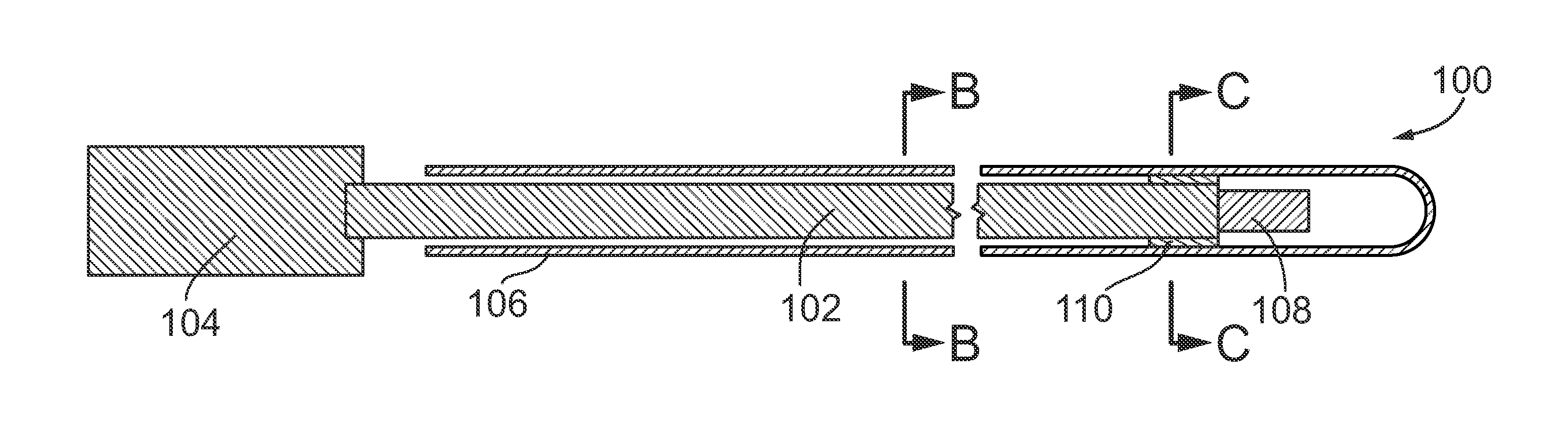
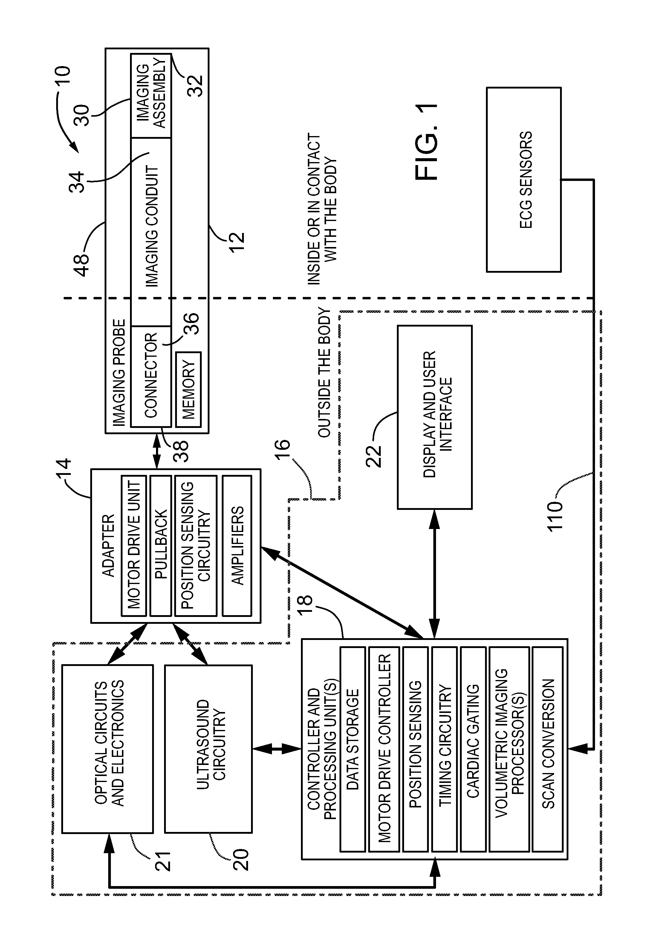
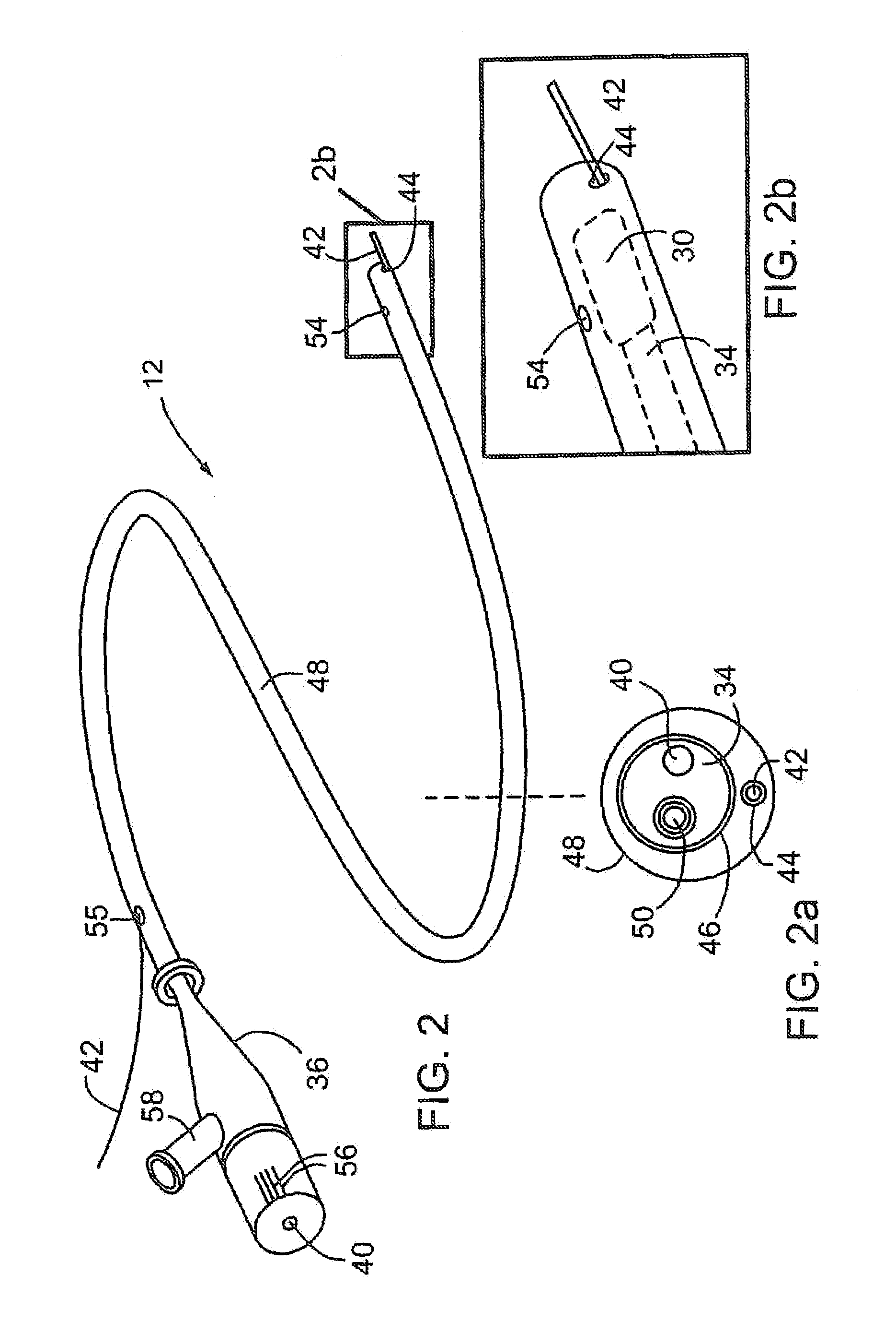
[0066]Without limitation, the majority of the systems described herein are directed to an imaging probe using either optical or ultrasonic (or both) imaging incorporating mechanisms to reduce non-uniform rotational distortion (NURD). The imaging probe includes means for estimating a rotational motion near the distal end of a rotating shaft within the probe. As required, embodiments of the present invention are disclosed herein. However, the disclosed embodiments are merely exemplary, and it should be understood that the invention may be embodied in many various and alternative forms.

[0067]The Figures are not to scale and some features may be exaggerated or minimized to show details of particular elements while related elements may have been eliminated to prevent obscuring novel aspects. Therefore, specific structural and functional details disclosed herein are not to be interpreted as limiting but merely as a basis for the claims and as a representative basis for teaching one skille...


PUM


Abstract

The present invention provides minimally invasive imaging probe / medical device having a frictional element integrated therewith for reducing non-uniform rotational distortion near the distal end of a medical device, such as an imaging probe which undergoes rotational movement during scanning of surrounding tissue in bodily lumens and cavities.

Description

CROSS-REFERENCE TO RELATED APPLICATION[0001]This application claims priority to U.S. Provisional Application No. 61 / 202,742, filed on Mar. 31, 2009, the entire contents of which are incorporated herein by reference.FIELD OF THE INVENTION[0002]The present invention relates generally to the field of minimally invasive medical devices, including imaging devices for imaging mammalian tissues and structures using high frequency ultrasound, such as intravascular ultrasound (IVUS) and optical imaging methods such as optical coherence tomography (OCT) which incorporate friction devices to improve transmission of torque along a rotational drive shaft.BACKGROUND OF THE INVENTION[0003]High resolution imaging of the interior of the body (or for dermatologic or opthalmology applications not restricted to the interior) serves multiple purposes, including any of i) assessing tissue structures and anatomy; ii) planning and / or guiding interventions on localized regions of the body; and iii) assessin...

Claims


Application Information

Patent Timeline
Patent Type & Authority Patents(United States)
IPC IPC(8): A61B5/00A61B1/00A61B5/02A61B8/00A61B8/08A61B8/12A61B18/14A61B18/18
CPCA61B18/18A61B5/0066A61B5/0084A61B5/02007A61B8/12A61B8/4461A61B5/6852A61B1/00096A61B1/00172A61B8/0883A61B8/0891A61B8/543A61B18/1492A61B8/445A61M25/0113A61M39/24
Inventor COURTNEY, BRIAN KENT
Owner SUNNYBROOK HEALTH SCI CENT
Why Eureka
Try Eureka