
MRI-guided localization and/or lead placement systems, related methods, devices and computer program products

a technology of localization and mri, applied in the field of placement/localization of interventional medical devices and/or therapies, can solve the problems of system unsuitability for use in a magnetic resonance imaging (mri) environment, device compatibility, and mri image distortion

Active Publication Date: 2015-05-26
CLEARPOINT NEURO INC
View PDF162 Cites 57 Cited by
  • Summary
  • Abstract
  • Description
  • Claims
  • Application Information

AI Technical Summary

Benefits of technology

Enables accurate and efficient placement of interventional devices, such as DBS leads, in MRI environments, improving clinical outcomes by reducing procedural time and increasing the effectiveness of treatments like DBS for conditions like Parkinson's disease.

Problems solved by technology

However, currently available lead systems may be unsuitable to use in a magnetic resonance imaging (MRI) environment.
For example, the devices may not be MRI compatible, i.e., they may contain ferromagnetic materials, which may distort the MRI images.
Also, currently available lead / probe / cable systems may be susceptible to unwanted induced RF and / or AC current and / or localized heating of the tissue.
Also, the problem of unwanted RF deposition may increase as higher magnetic fields, such as 3 T systems, become more common for MRI imaging (the RF pulses having shorter wavelengths).
These procedures can be long in duration and may have reduced efficacy as it has been reported that, in about 30% of the patients implanted with these devices, the clinical efficacy of the device / procedure is less than optimum.

Method used


Image

  • MRI-guided localization and/or lead placement systems, related methods, devices and computer program products
  • MRI-guided localization and/or lead placement systems, related methods, devices and computer program products
  • MRI-guided localization and/or lead placement systems, related methods, devices and computer program products

Examples


Embodiment Construction

[0008]Embodiments of the present invention are directed to medical tools, systems and methods useful for MRI-guided localization and / or placement of interventional therapies and / or devices.

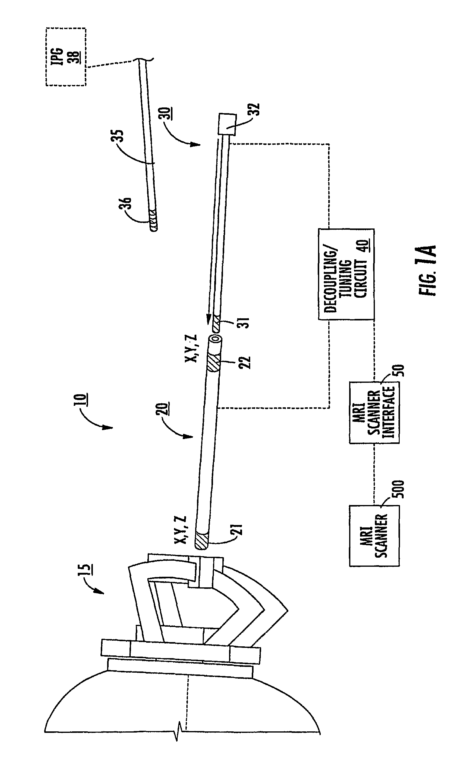
[0009]Some embodiments of the present invention provide systems that utilize at least one MRI to visualize (and / or locate) a therapeutic region of interest (such as, for example, a target site inside the brain) and utilize at least one MRI to visualize (and / or locate) an interventional tool or tools that are used to deliver a therapy and / or to place a chronically (typically permanently) implantable device that will deliver a therapy.

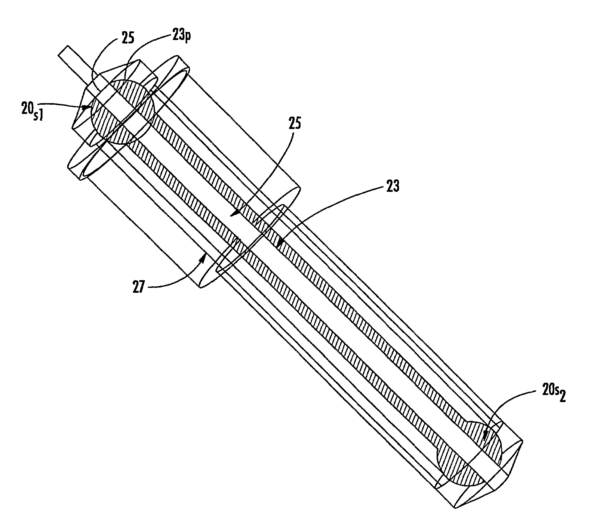
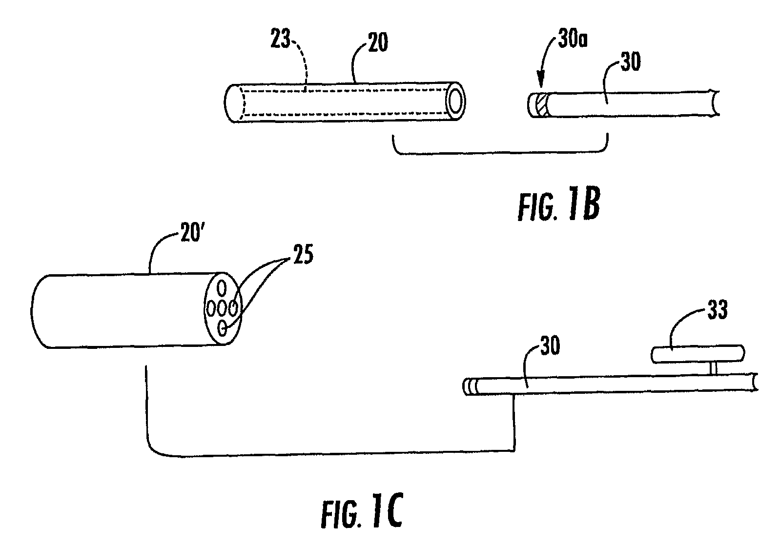
[0010]Some embodiments include a targeting cannula with a lumen sized and configured to slidably receive an elongate probe. The elongate probe can include a recording electrode (e.g., transducer) and / or a stimulation electrode. Optionally, the targeting cannula and / or probe or components thereof may be MRI visible.

[0011]Some embodiments of the present invention can be ...


PUM


Abstract

MRI compatible localization and / or guidance systems for facilitating placement of an interventional therapy and / or device in vivo include: (a) a mount adapted for fixation to a patient; (b) a targeting cannula with a lumen configured to attach to the mount so as to be able to controllably translate in at least three dimensions; and (c) an elongate probe configured to snugly slidably advance and retract in the targeting cannula lumen, the elongate probe comprising at least one of a stimulation or recording electrode. In operation, the targeting cannula can be aligned with a first trajectory and positionally adjusted to provide a desired internal access path to a target location with a corresponding trajectory for the elongate probe. Automated systems for determining an MR scan plane associated with a trajectory and for determining mount adjustments are also described.

Description

RELATED APPLICATIONS[0001]This application is a 35 USC 371 national phase application of PCT / US2006 / 045752, filed Nov. 29, 2006, which claims the benefit of U.S. Provisional Patent Application Ser. No. 60 / 740,353, filed Nov. 29, 2005, the contents of which are hereby incorporated by reference as if recited in full herein.FIELD OF THE INVENTION[0002]The present invention relates to placement / localization of interventional medical devices and / or therapies in the body. Embodiments of the present invention may be particularly suitable for placing neuro-modulation leads, such as Deep Brain Stimulation (“DBS”) leads, implantable parasympathetic or sympathetic nerve chain leads and / or CNS stimulation leads.BACKGROUND OF THE INVENTION[0003]Deep Brain Stimulation (DBS) is becoming an acceptable therapeutic modality in neurosurgical treatment of patients suffering from chronic pain, Parkinson's disease or seizure, and other medical conditions. Other electro-stimulation therapies have also bee...

Claims


Application Information

Patent Timeline
Patent Type & Authority Patents(United States)
IPC IPC(8): A61B5/05A61B5/00A61B5/0476A61B5/055A61B17/00A61B19/00A61N1/05A61N1/08A61N1/37A61N1/372G01R33/28G01R33/34G01R33/48
CPCA61B5/055A61B5/0476A61B5/6864A61B5/6865A61B19/201A61N1/0529A61N1/0534A61N1/0539G01R33/286G01R33/287G01R33/34084A61B2017/00039A61B2019/5454A61N1/3718A61N2001/086G01R33/288G01R33/4808A61N1/372A61B34/20A61B2090/374A61B2034/2051A61B2090/3954A61N1/086A61B90/11A61B5/369A61B5/37A61B5/6847A61B5/7435A61B34/10A61B2034/107A61B90/14A61M39/08A61N1/08G01R33/285
Inventor KARMARKAR, PARAG V.JENKINS, KIMBLE
Owner CLEARPOINT NEURO INC
Learn More