

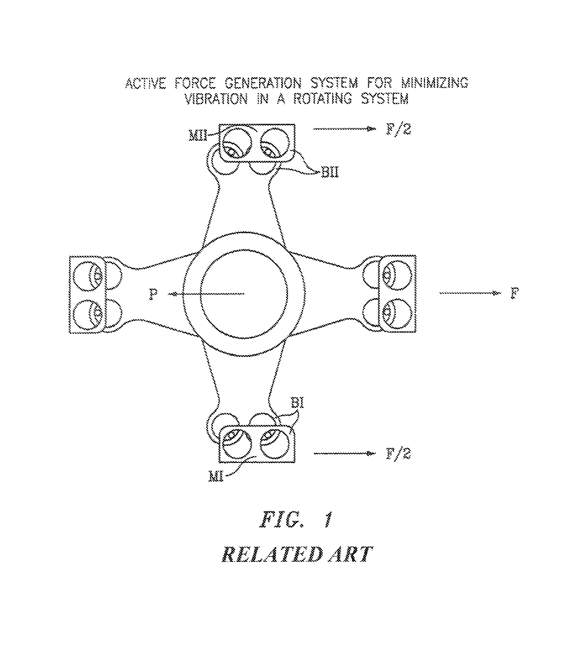
Active force generation system for minimizing vibration in a rotating system
a technology of active force generation and rotating system, which is applied in the field of isolating systems of vibration, can solve problems such as structural fatigue, premature failure of system components, and potential damage or disturbing, and achieve the effect of minimizing system weigh
- Summary
- Abstract
- Description
- Claims
- Application Information
AI Technical Summary
Benefits of technology
Problems solved by technology
Method used
Image

Examples
Embodiment Construction
[0019]The isolation system of the present invention is described in the context of a helicopter rotor system, such as that employed in an Army BLACK HAWK helicopter produced by Sikorsky Aircraft Corporation. One skilled in the art, however, will appreciate that the present invention has utility in any rotating system which produces vibratory loads (noise). The invention is especially useful in rotating systems that produce large vibratory loads that vary depending upon different operating regimes or variable operating speeds.
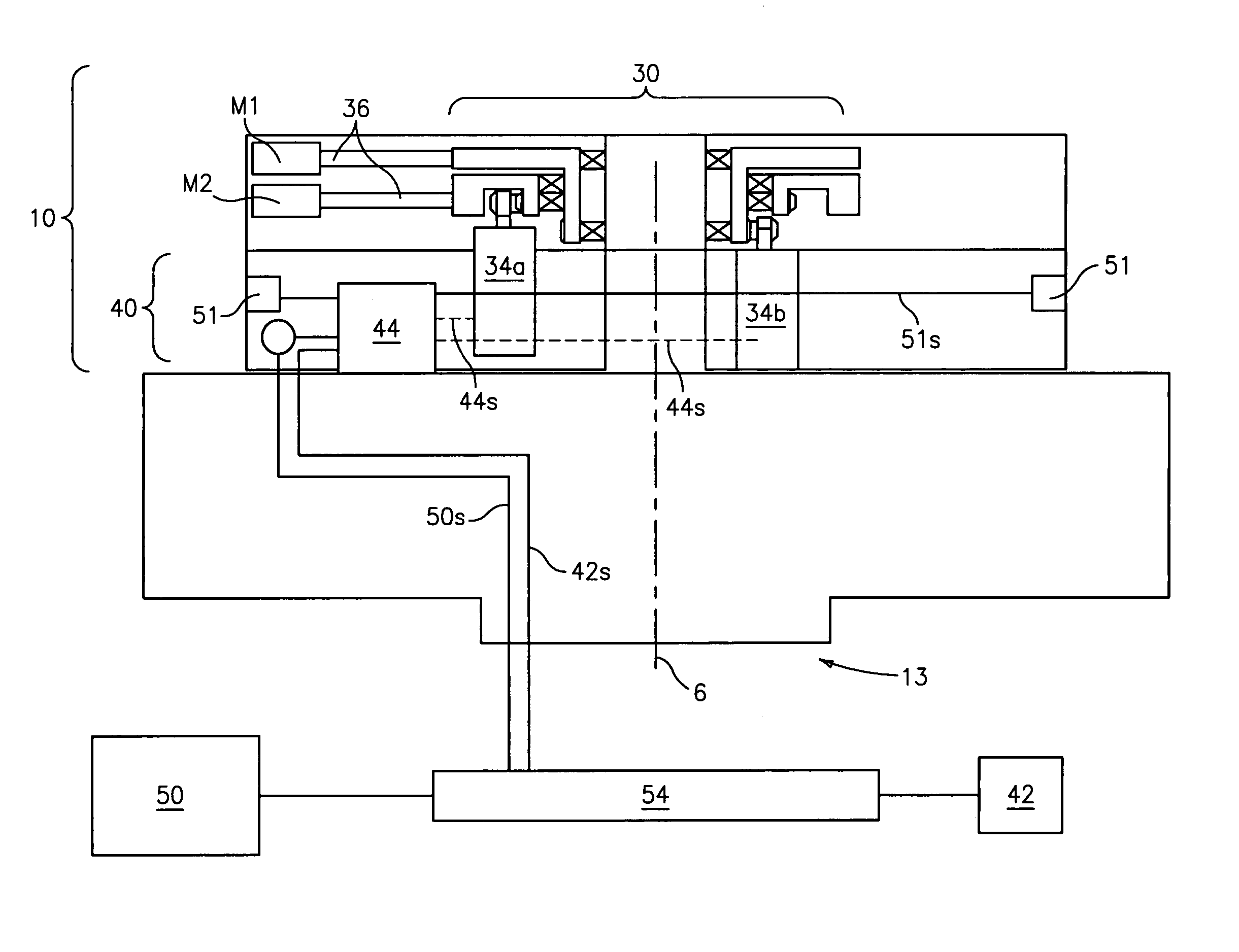
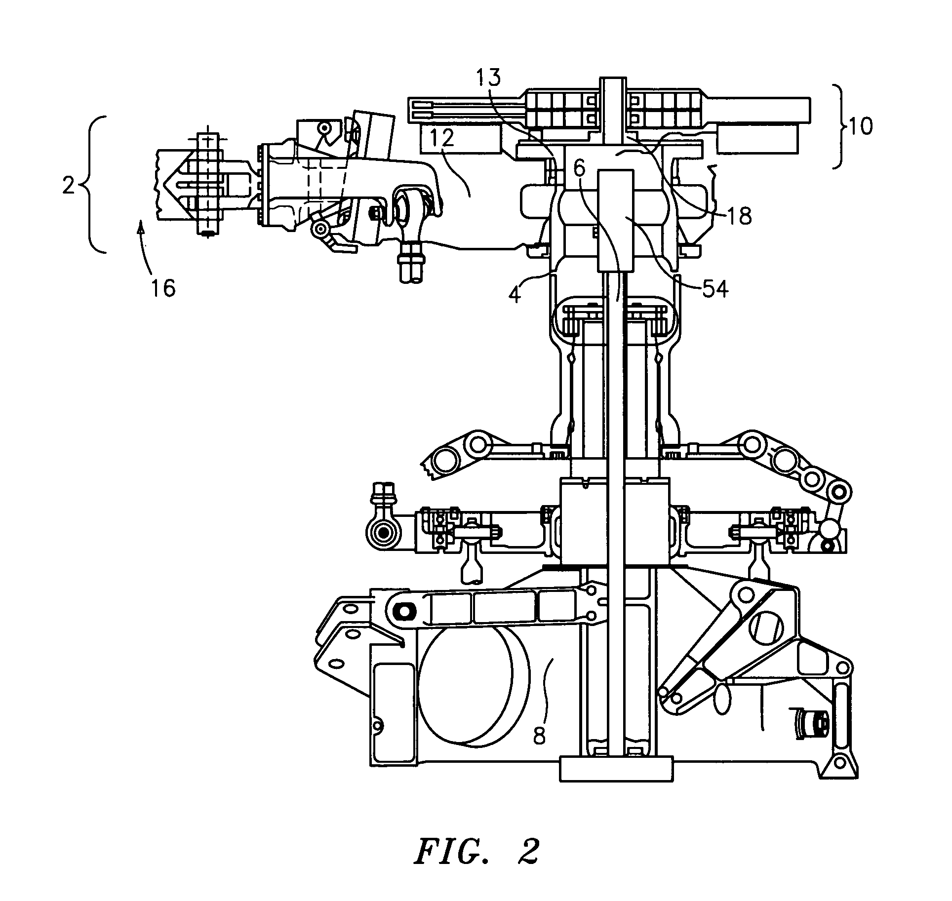
[0020]Referring to FIG. 2, the vibration isolation system 10 is disposed in combination with a rotary-wing aircraft main rotor system 2 having a main rotor shaft 4 (rotating system member) that is driven about a rotational axis 6 by a torque driving transmission 8. In the described embodiment, the rotor system 2 includes a hub 12 having four radial arms that mount to and drive each rotor blade 16. The vibration isolation system 10 is mounted to a flanged end 13 ...
PUM
 Abstract
Description
Claims
Application Information