Hybrid electric aircraft

Inactive Publication Date: 2020-01-16
ROLLS ROYCE PLC
View PDF0 Cites 2 Cited by
  • Summary
  • Abstract
  • Description
  • Claims
  • Application Information

AI Technical Summary

Problems solved by technology

In other words, the excess energy generating capacity of the internal combustion engine/generator combination at some parts of the flight cycle can

Method used


Image

  • Hybrid electric aircraft
  • Hybrid electric aircraft
  • Hybrid electric aircraft

Examples


Embodiment Construction

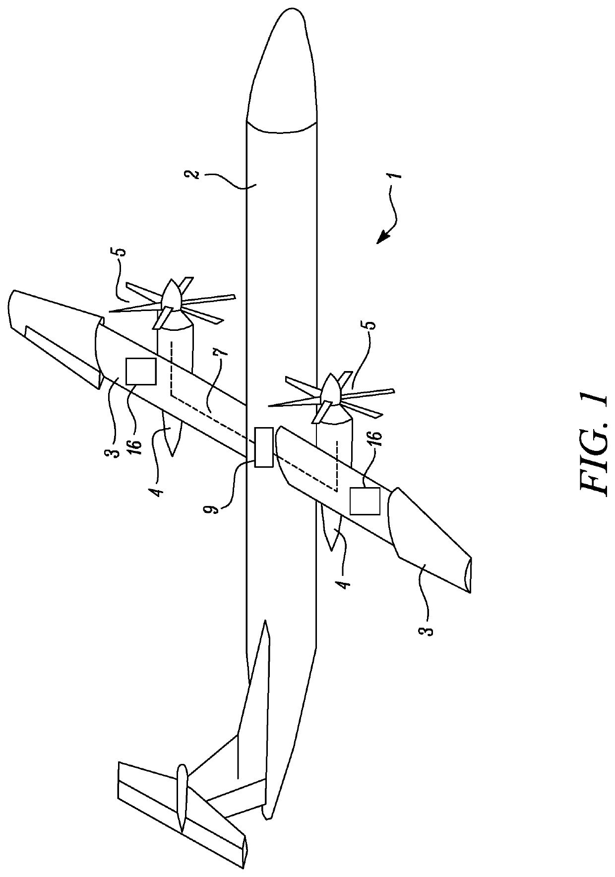
[0025]With reference to FIGS. 1 and 2, an aircraft 1 is shown. The aircraft 1 comprises a fuselage 2, wings 3, and a propulsion system comprising a pair of first propulsors 4.

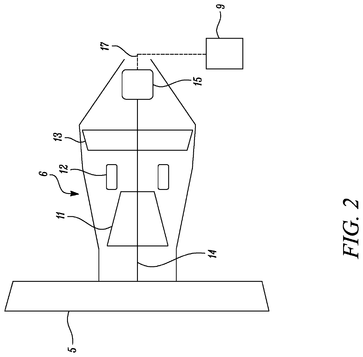
[0026]Each propulsor 4 comprises a propeller 5 which is, at least in part, driven by an electrical machine 15 which can be operated as either a motor or a generator. The electrical machine 15 could be of any suitable type, such as permanent magnet direct current (DC), and alternating current (AC) brushless, and is configured to be operable as either an electric generator or as a motor.

[0027]An electrical power storage unit in the form of a battery 9 is electrically coupled to both the electric motor / generators 15 via interconnectors 7. The interconnectors 7 may carry either DC or AC current.

[0028]When acting as a generator, the electrical machine 9 is driven by an internal combustion engine in the form of a gas turbine engine 6. Each gas turbine engine 6 comprises a compressor 11, combustor 12 and turbine 13 in...


PUM


Abstract

An aircraft propulsion system. The system comprises an internal combustion engine configured to drive a first propulsor and an electric generator. The system further comprises an electric motor or motors each configured to be powered by electric power provided by the generator, and configured to drive the first propulsor and/or a second propulsor. An electrical energy storage unit is provided, and is configured to store electrical energy supplied from the generator and supply electrical power to the electric motor. At maximum take-off power, the electric motor provides between 5% and 20% of total maximum aircraft propulsive take-off power.

Description

CROSS-REFERENCE TO RELATED APPLICATIONS[0001]This application is based upon and claims the benefit of priority from British Patent Application No. GB 1811294.6, filed on 10 Jul. 2018, the entire contents of which are incorporated by reference.BACKGROUNDTechnical Field[0002]The present disclosure concerns a hybrid aircraft propulsion system, and an aircraft comprising the propulsion system.Description of the Related Art[0003]Traditionally, aircraft have been propelled by one or more propulsors such as fans or propellers driven by internal combustion engines such as gas turbine engines or piston engines. Conventionally, the propulsor is driven by a direct drive shaft, or a reduction gearbox.[0004]Recently, it has been proposed to provide an electric motor to drive the propulsor, with power for the electric motor being provided by a generator driven by the internal combustion system. Such a system is known as a “hybrid electric propulsion system”. A battery or other power storage unit ...

Claims


Application Information

Patent Timeline
IPC IPC(8): B64D27/02B64D27/10B64D27/24H02K11/00H02K7/20H02K7/18
CPCB64D27/02H02K7/20H02K7/1823B64D27/10B64D27/24B64D2027/026H02K11/0094B60L50/16B60L2200/10F01D15/10F02C6/14F02C6/206F02K5/00F05D2220/76F05D2260/42F05D2270/07Y02T10/7072Y02T50/40Y02T50/60
Inventor CHUNG, JAE-HOONRAFFAELLI, LORENZO
Owner ROLLS ROYCE PLC
Why Eureka
Try Eureka