Device and method for fusion beat detection

a technology of fusion beat and detection device, which is applied in the field of heart monitoring and/or therapy devices, can solve the problems of ventricular pace, waste of battery power, inefficient myocardial contraction, etc., and achieve the effect of improving fusion beat detection and facilitating cardiac rhythm managemen

Inactive Publication Date: 2015-06-09
BIOTRONIK SE & CO KG
View PDF18 Cites 0 Cited by
  • Summary
  • Abstract
  • Description
  • Claims
  • Application Information

AI Technical Summary

Benefits of technology

[0017]One or more embodiments of the invention are related to a heart monitoring and / or therapy device with improved fusion beat detection. Objectives of the invention according to at least one embodiment of the invention include providing a heart monitoring and / or therapy device with a capability to quantify the degree of fusion should it occur, and providing a heart monitoring and / or therapy device with a novel feature to quantify the burden of fusion to facilitate cardiac rhythm management.
[0035]Embodiments of the invention provide a novel method and system for fusion beat detection and quantification. Embodiments include at least the following unique advantages:
[0038]Embodiments of the invention may evaluate the morphological similarity between IEGM and templates based on correlation analysis of the whole waveform, not limited to specific morphological features (e.g. slope, peak amplitude, zero-crossing, etc.) or partial segment of the waveform. This may lead to more accurate assessment of the morphological similarity between signals.
[0040]Using accurate fusion beat detection and fusion quantification, at least one embodiment of the invention may provide new statistical information (such as fusion beat percentage and fusion burden) that may be used to facilitate cardiac rhythm management. Therefore, embodiments of the invention may lead to a novel diagnostic feature for cardiac rhythm management (CRM) products.

Problems solved by technology

However, there is always a possibility that a ventricular pace is issued while there is also an intrinsic depolarization.
First, cardiac stimulation that leads to fusion, typically, may represent a waste of battery power.
Second, fusion beat, typically, may disrupt the normal cardiac conduction and lead to inefficient myocardial contraction.
Third, typically, for an implantable device that implements automatic pacing capture management based on analysis of evoked response (that is the electrogram resulting from a stimulated (paced) depolarization), fusion beat is undesired because it may distort the electrogram signal.
Therefore, fusion beat detection generally poses a particular technical challenge for implantable cardiac devices.
However, the RV pacing statistics (e.g. number and frequency of RV pacing) maintained by the pacemaker may be misleading: Patient A who has 20% RV pacing may have lower risk of pacing-induced HF than patient B who has only 10% RV pacing—if the RV paces in patient A are mainly fusion beats dominated by intrinsic activity, whereas the majority of RV paces in patient B are fully captured beats.
However, the BiV or LV pacing percentage generally may not reflect the true effectiveness of CRT, because that metric could be inflated by fusion beats, which may be common during episodes of atrial fibrillation with intrinsic AV conduction.
This approach has several limitations.
First, selected features cannot fully characterize the morphology of the IEGM signal.
Therefore, a stable LOC template may not be available.
However, either assumption may not be true.
However, a captured pace can still result in fusion beat.
Therefore, this approach can misclassify a fusion beat to a captured beat.

Method used


Image

  • Device and method for fusion beat detection
  • Device and method for fusion beat detection
  • Device and method for fusion beat detection

Examples


Embodiment Construction

[0060]The following description is of the best mode presently contemplated for carrying out at least one embodiment of the invention. This description is not to be taken in a limiting sense, but is made merely for the purpose of describing the general principles of the invention. The scope of the invention should be determined with reference to the claims.

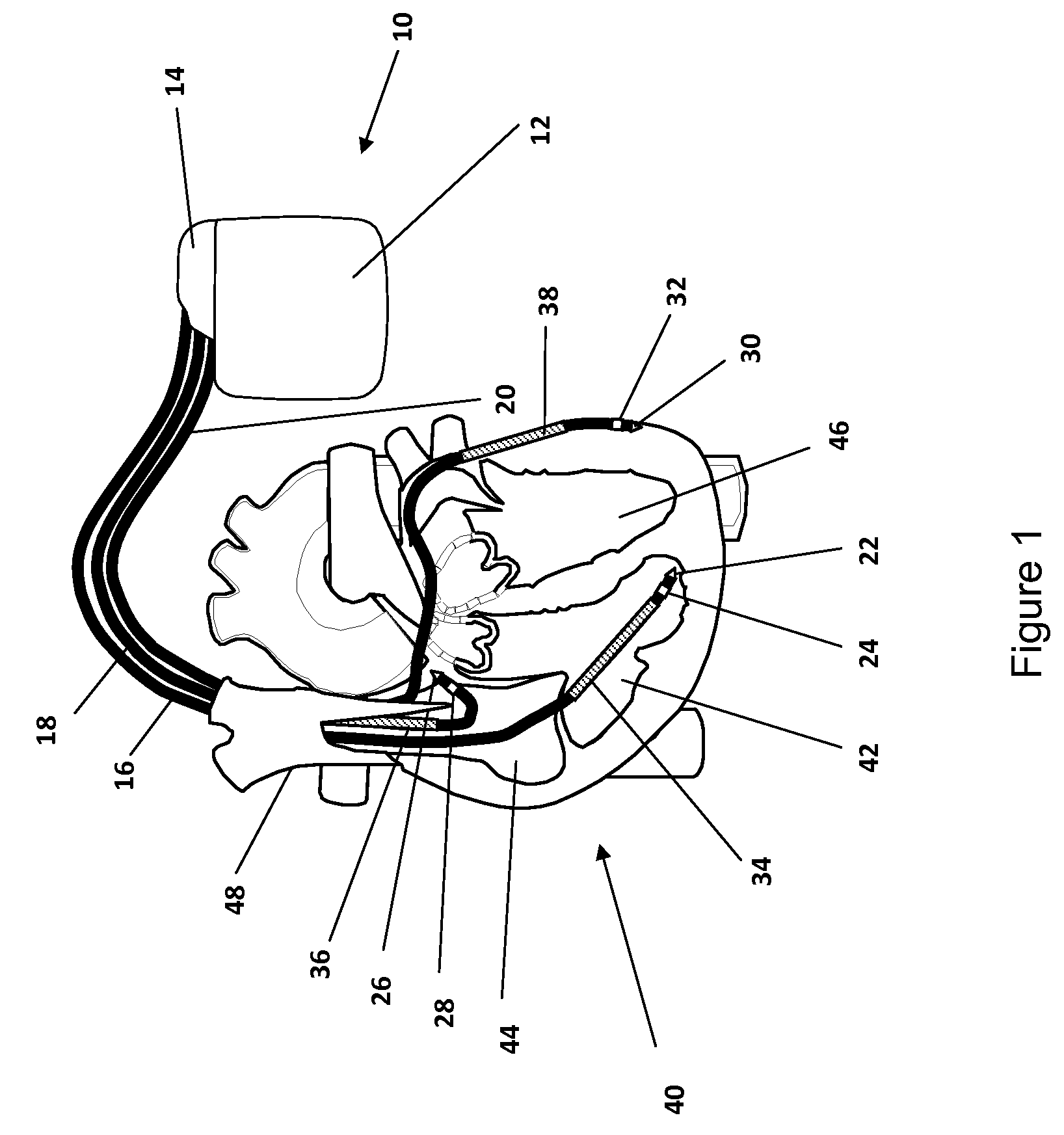
[0061]FIG. 1 shows a schematic illustration of an ICD system. As shown in FIG. 1, the device according to one or more embodiments includes a stimulator 10 including a housing or case 12 and a header 14.

[0062]In at least one embodiment of the invention, the heart stimulator 10 may be connected to three electrode leads, namely a right ventricular electrode lead 16, a right atrial electrode lead 18 and a left ventricular electrode lead 20.

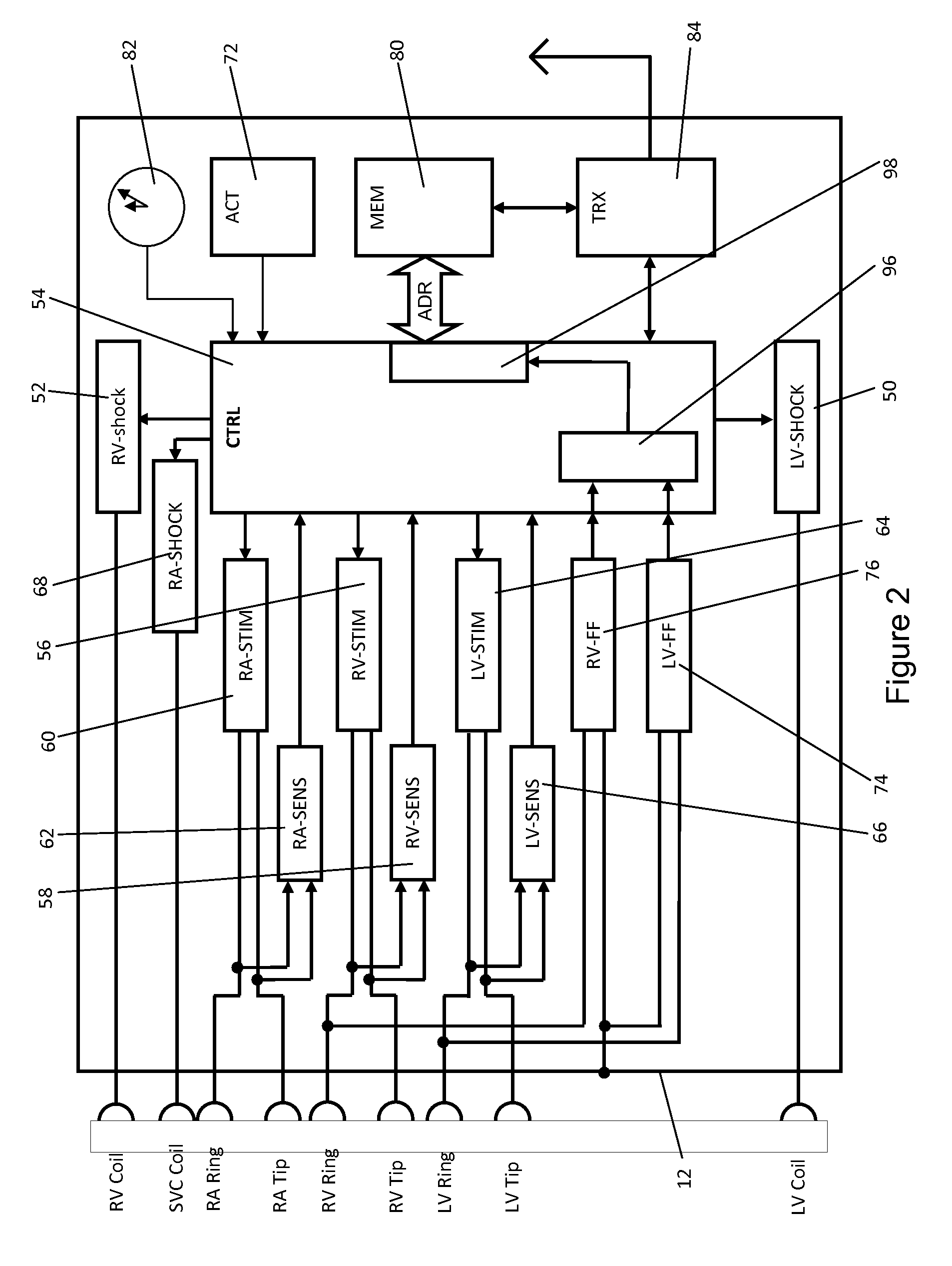
[0063]FIGS. 1 and 2, according to embodiments of the invention, illustrate the pacing system that includes a heart stimulator 10 and the connected leads 16, 18, 20. The right atrial electrode lead 18...


PUM


Abstract

A heart monitoring and / or therapy device for detecting and quantifying fusion beats, wherein the device includes an IEGM signal sensing channel that puts out a recorded IEGM signal and an evaluation unit operatively connected to the IEGM signal sensing channel that detects fusion beats. The evaluation unit comprises or is connected to a template memory including at least a first template electrogram signal and a second template electrogram signal. The evaluation unit compares the recorded IEGM signal with both, the first and the second template electrogram signal and determines at least a first degree of similarity reflecting the similarities between the recorded electrogram signal and the first template electrogram signal, and a second degree of similarity reflecting the similarities between the recorded electrogram signal and the second template electrogram signal. The evaluation unit then calculates a fusion index (FI) from the at least two degrees of similarity.

Description

[0001]This application claims the benefit of U.S. Provisional Patent Application 61 / 754,982, filed on 22 Jan. 2013, the specification of which is hereby incorporated herein by reference.BACKGROUND OF THE INVENTION[0002]1. Field of the Invention[0003]At least one embodiment of the invention generally relates to a heart monitoring and / or therapy device that is configured to detect fusion beats.[0004]2. Description of the Related Art[0005]Typically, fusion beat represents the merging of two different cardiac excitation waves. For patients with implantable cardiac pacemakers or defibrillators, generally, fusion beat is often caused by the merging of intrinsic cardiac depolarization and the excitation wave generated by the pacing device that has generated a ventricular pace (VP).[0006]Generally, a ventricular pace may cause a stimulated ventricular depolarization of the heart muscle cells and thus a contraction of the myocardium if the strength of the ventricular pace is above a stimulat...

Claims


Application Information

Patent Timeline
Patent Type & Authority Patents(United States)
IPC IPC(8): A61B5/0452A61N1/37A61B5/0432
CPCA61B5/04525A61N1/3702A61N1/3712A61B5/0432A61B5/0452A61B5/35A61B5/333A61B5/349
Inventor LIAN, JIEMUESSIG, DIRK
Owner BIOTRONIK SE & CO KG
Why Eureka
Try Eureka