Permanent magnet rotating electric machine

a permanent magnet, rotating electric machine technology, applied in the direction of magnetic circuit rotating parts, magnetic circuit shape/form/construction, liquid fuel engines, etc., can solve the problems of magnet and rotor deformation or damage, air bubbles in the filling portion expanding and contracting, etc., to reduce fluid friction

Active Publication Date: 2015-06-09
HITACHI IND PROD LTD
View PDF19 Cites 1 Cited by
  • Summary
  • Abstract
  • Description
  • Claims
  • Application Information

AI Technical Summary

Benefits of technology

[0009]JP-2006-311730-A discloses a magnet insertion hole shape having a filling portion between a magnet insertion hole in a rotor and a magnet and air gaps disposed on both end portions of the magnet. This allows an adhesive to be poured into a gap between the magnet and an electrical steel sheet to thereby even out a surface of the electrical steel sheet in contact with the magnet with the adhesive. An excessive stress occurring locally in the magnet can thereby be reduced.
[0013]An object of the present invention is to provide a permanent magnet pump motor that is operated in a condition of being packed with LNG and that prevents a magnet and a rotor from being deformed or damaged and reduces fluid friction by having a small-diameter rotor.
[0015]According to the present invention, a permanent magnet pump motor that takes into consideration the linear expansion of the permanent magnet and the electrical steel sheet and achieves reduced fluid friction can be obtained.

Problems solved by technology

However, when the machine is used under an extremely low temperature condition, such as with the LNG, air bubbles present in the filling portion expand and contract as affected by a sudden change in temperature from room temperature to low temperature or vice versa.
As a result, stress on the magnet and the rotor occurs, causing the magnet and the rotor to be deformed or damaged.

Method used


Image

  • Permanent magnet rotating electric machine
  • Permanent magnet rotating electric machine
  • Permanent magnet rotating electric machine

Examples


first embodiment

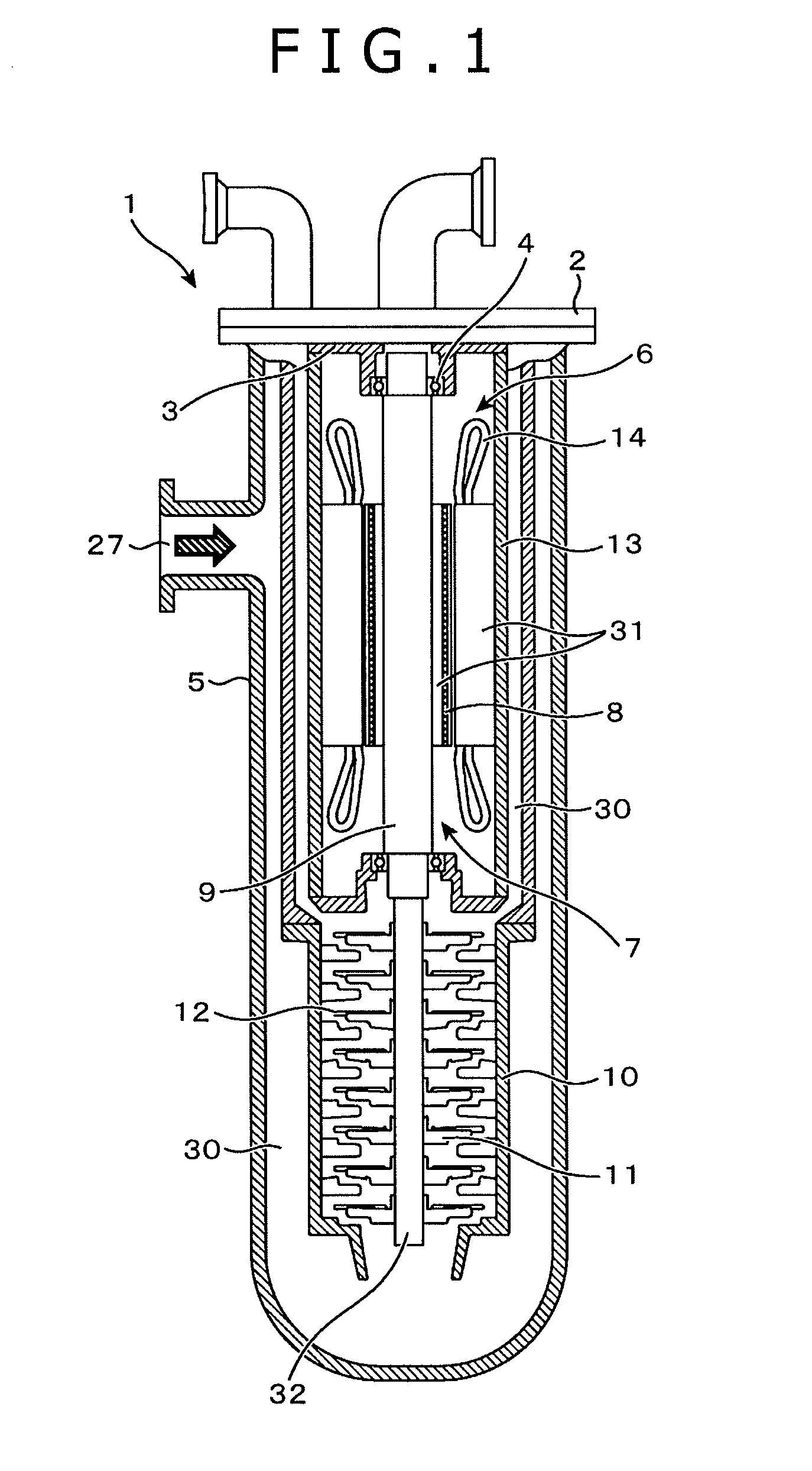
[0035]FIG. 1 is a cross-sectional view showing a permanent magnet pump motor according to a first embodiment of the present invention. The permanent magnet pump is applied to an LNG plant delivering power on the order of several megawatts. Three-phase alternating current power is supplied from an inverter 25 to the permanent magnet pump motor that operates at a speed in a range from 500 to 7000 min−1.

[0036]As shown in FIG. 1, a motor portion is disposed inside the pump and the pump is operated in a vertical position with LNG at about −162° C. packed therein. A permanent magnet pump motor 1 is covered in an outermost case called a pot 5 and a head cover 2 for hermetically sealing components disposed inside the pot 5. A stage case 10 is disposed inside the pot 5. A flow path 30 through which LNG 27 flows is disposed between the pot 5 and the stage case 10. An impeller 11, a diffuser 12, and a motor case 13 that assume major pump components are disposed inside the stage case 10.

[0037]T...

second embodiment

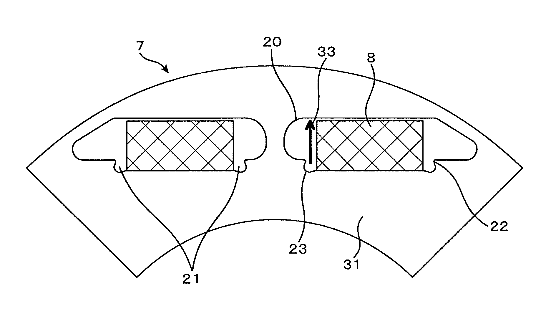
[0052]FIGS. 5 to 7 are illustrations showing protections for the permanent magnet 8 according to a second embodiment of the present invention. Referring to FIG. 5, a coating 24 is applied to the entire permanent magnet 8. As described with reference to the first embodiment of the present invention, the air gaps 21 are disposed on both ends of the permanent magnet 8. The permanent magnet 8 is therefore expected to be moved by a centrifugal force. The permanent magnet 8, if moved in the magnet insertion hole 20, may have a damaged surface.

[0053]In the second embodiment of the present invention, the coating 24 is applied to the surface of the permanent magnet 8, thereby preventing the permanent magnet 8 from being damaged when moved in the magnet insertion hole 20. If the permanent magnet 8 is moved in the magnet insertion hole 20, the coating 24 can be shaved. Preferably, therefore, the coating 24 has a thickness as thick as possible. The coating 24 is also required to be formed of a ...

third embodiment

[0057]FIG. 8 is an illustration showing a protection for the permanent magnet 8 according to a third embodiment of the present invention. Referring to FIG. 8, liners 26 are inserted at upper and lower portions in the magnetization direction of the permanent magnet 8 when the permanent magnet 8 is inserted in the magnet insertion hole 20.

[0058]Since the electrical steel sheet 31 is a laminate, microscopic irregularities exist inside the magnet insertion hole 20. The irregularities scratch or separate the coating when the permanent magnet 8 is inserted into the magnet insertion hole 20. The liners 26 prevent this from occurring.

[0059]For example, metal or thin Teflon, preferably having a smooth surface, is suitable for the material of the liner 26. If a metal liner 26 is used, harmonics affect to produce eddy current to thereby increase loss; however, splitting the liner 26 will reduce loss caused by the eddy current.

[0060]Heat generated from the liner 26 due to the eddy current does ...


PUM


Abstract

A permanent magnet rotating electric machine includes a rotor and a stator. The rotor includes: a permanent magnet forming a single pole within a rotor core of the rotor, the permanent magnet being divided into two divided permanent magnets; a connecting portion assuming an electrical steel sheet disposed between the two divided permanent magnets; and magnet insertion holes in which the permanent magnets are inserted. In the rotor, the magnet insertion holes are shaped to include: air gaps at both end portions in a width direction of the permanent magnet, each air gap being formed between a surface of the permanent magnet extending perpendicularly to the magnetization direction and a surface of the electrical steel sheet facing the surface of the permanent magnet; a shoulder portion disposed on the facing surface; and another air gap extending toward a rotor outside diameter side and the magnetic pole center side.

Description

BACKGROUND OF THE INVENTION[0001]1. Field of the Invention[0002]The present invention relates to a permanent magnet pump motor having a permanent magnet rotating electric machine that includes a rotor and a stator, and a permanent magnet pump motor system incorporating the same.[0003]2. Description of the Related Art[0004]Unlike ordinary pump systems, LNG pump motors have an integrated structure in which a rotor, a stator, an impeller, and a diffuser are built into a pump casing. Such a LNG pump motor is operated in an LNG fluid having a temperature of −162° C. and thus there arise problems inherent in low temperatures.[0005]Rare-earth magnets, such as neodymium magnets and praseodymium magnets, in particular, have a property that the permanent magnet contracts in a magnetization direction and expands in a direction perpendicular to the magnetization direction at low temperatures.[0006]This requires that linear expansion of the electrical steel sheet and the permanent magnet be take...

Claims


Application Information

Patent Timeline
Patent Type & Authority Patents(United States)
IPC IPC(8): H02K1/27H02K7/14
CPCH02K1/27H02K1/276H02K7/14F04D29/5806F04D13/06
Inventor KORI, DAISUKEIIZUKA, MOTONOBUFUKUNAGA, ATSUSHI
Owner HITACHI IND PROD LTD
Why Eureka
Try Eureka