Optical filter and imaging device comprising the same

a technology applied in the field of optical filters and imaging devices, can solve the problems of low glass transition temperature and insufficient heat resistance of these resins, and achieve the effects of high heat resistance, reduced retardation, and improved heat resistan

Active Publication Date: 2015-06-16
JSR CORPORATIOON
View PDF15 Cites 0 Cited by
  • Summary
  • Abstract
  • Description
  • Claims
  • Application Information

AI Technical Summary

Benefits of technology

[0029]The optical filter of the present invention has superior light transmittance, heat resistance, heat coloration resistance, and mechanical strength, and has little retardation in the thickness direction. As a result, the optical filter of the present invention can be suitably used in imaging devices.

Problems solved by technology

However, the glass transition temperature of these resins is low, from 70 to 180° C. and, in some cases, heat resistance is not sufficient.

Method used


Image

  • Optical filter and imaging device comprising the same
  • Optical filter and imaging device comprising the same
  • Optical filter and imaging device comprising the same

Examples


example 1

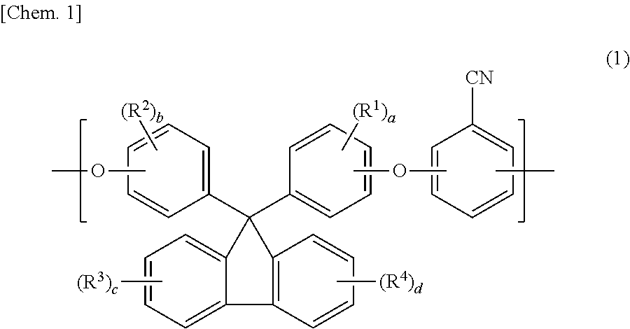
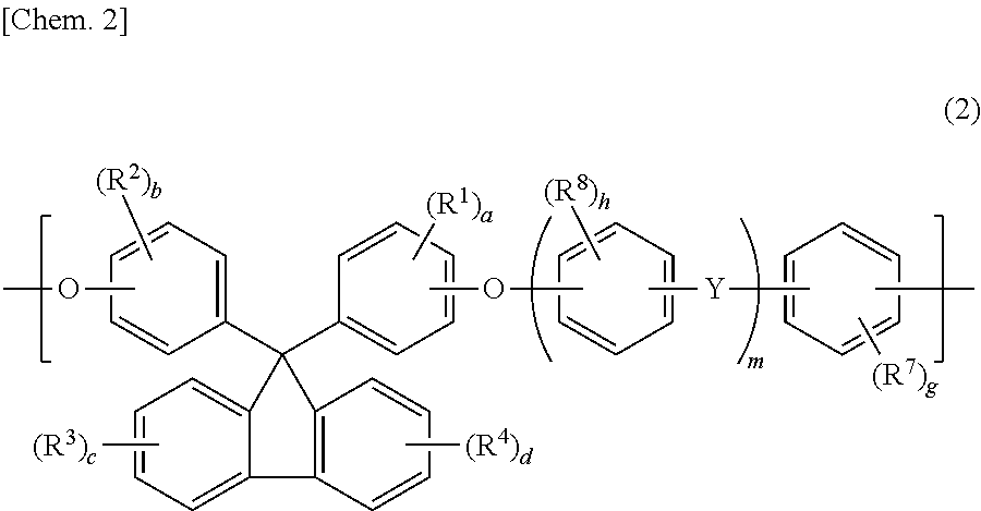
[0231]35.12 g (0.253 mol) of 2,6-difluorobenzonitrile (hereinafter also referred to as “DFBN”), component (A); 70.08 g (0.200 mol) of 9,9-bis(4-hydroxyphenyl)fluorene (hereinafter also referred to as “BPFL”) and 5.51 g (0.050 mol) of resorcinol (hereinafter also referred to as “RES”), component (B); 41.46 g (0.300 mol) of potassium carbonate; 443 g of N,N-dimethyl acetamide (hereinafter also referred to as “DMAc”); and 111 g of toluene were added to a 3 L four-neck flask. Then, a thermometer, a stirrer, a three-way cock with a nitrogen introducing tube, a Dean-Stark tube, and a cooling tube were attached to the four-neck flask.

[0232]Next, the flask was purged with nitrogen and, thereafter, the resultant solution was reacted for 3 hours at 140° C. The generated water was constantly removed via the Dean-Stark tube. The temperature was raised gradually to 160° C. after the generation of water ceased and the solution was reacted at this temperature for 6 hours.

[0233]After the solution w...

example 2

[0237]Other than using 11.41 g (0.050 mol) of 2,2-bis(4-hydroxyphenyl)propane instead of the 5.51 g of RES, Example 2 was carried out the same as Example 1. Properties of the obtained polymer and evaluation film are shown in Table 1.

example 3

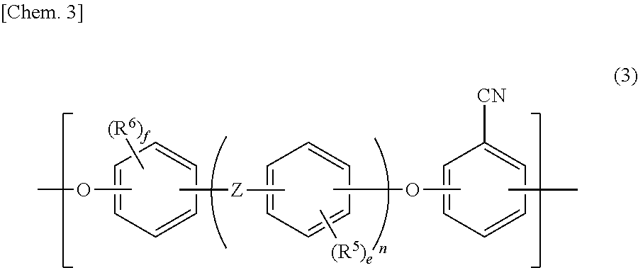
[0238]Other than using 78.84 g (0.225 mol) of BPFL and 8.41 g (0.025 mol) of 2,2-bis(4-hydroxyphenyl)-1,1,1,3,3,3-hexafluoropropane instead of 70.08 g of BPFL and 5.51 g of RES as the component (B), Example 3 was carried out the same as Example 1. Properties of the obtained polymer and evaluation film are shown in Table 1.


PUM


Abstract

An optical filter comprising a substrate and a dielectric multilayer film formed on at least one surface of the substrate, wherein the substrate comprises an aromatic polyether-based polymer having a glass transition temperature (Tg), measured via differential scanning calorimetry (DSC, heating rate: 20° C. / min), of from 230 to 350° C.

Description

TECHNICAL FIELD[0001]The present invention relates to an optical filter and an imaging device comprising the same.BACKGROUND ART[0002]Conventionally, optical filters have been used to correct luminosity factors and to prevent declines in resolution in video cameras, digital still cameras, mobile phones with camera features, and the like.[0003]For example, in video cameras, digital still cameras, mobile phones with camera features, and the like, solid-state image sensors for color images such as CCD and CMOS image sensors are used. Luminosity factor correction must be performed because silicon photodiodes, which are sensitive to near-infrared rays, are used in the light receiving portions of these solid-state image sensors and, and thus, in many cases, near-infrared ray cutoff filters are used.[0004]In light adjusting devices such as diaphragm devices, diaphragm and shutter devices used in the lens optical system of video cameras, digital still cameras, mobile phones with camera feat...

Claims


Application Information

Patent Timeline
Patent Type & Authority Patents(United States)
IPC IPC(8): G02B5/28G02B5/22
CPCG02B5/287G02B5/22G02B5/20G03B17/00
Inventor OKANIWA, MOTOKIUNO, TAKAAKIFUJITOMI, SHINTAROOKADA, TAKASHIOTSUKI, TOSHIHIRONAGAYA, KATSUYA
Owner JSR CORPORATIOON
Why Eureka
Try Eureka