Arteriovenous shunt having a flow control mechanism

a technology of flow control and shunt, which is applied in the field of arteriovenous (av) shunt assembly, can solve the problems of lung over-inflation, lung over-inflation, and shortness of breath, so as to reduce the rate of blood flow, and constrict the tubular shunt

Active Publication Date: 2015-06-30
MEDTRONIC VASCULAR INC
View PDF8 Cites 22 Cited by
  • Summary
  • Abstract
  • Description
  • Claims
  • Application Information

AI Technical Summary

Benefits of technology

[0007]Embodiments hereof relate to an arteriovenous shunt assembly that includes a tubular shunt, a flow control mechanism, and a subcutaneous control port. The flow control mechanism includes a pull wire having a distal portion disposed around the tubular shunt in at least one loop. The subcutaneous control port contains ends of the pull wire, and pulling on the wire causes the pull wire to selectively tighten around the tubular shunt and radially constrict the tubular shunt, thereby reducing the rate of blood flow through the fluid passageway of the tubular shunt.
[0008]Embodiments hereof also relate to a method for forming a fistular connection between first and second body vessels, the connection including means for adjusting the rate of blood flow therethrough. A shunt assembly is intravascularly delivered in its collapsed configuration to a tissue tract formed between the first second body vessels. The shunt assembly includes a tubular shunt that defines a fluid passageway between open first and second ends thereof and a flow control mechanism coupled to the shunt, wherein the flow control mechanism includes a continuous pull wire having a distal portion disposed around the tubular shunt in at least one loop. The tubular shunt is positioned through the tissue tract, and the tubular shunt is deployed to an expanded configuration. Shortening the pull wire tightens the at least one loop of the distal portion to radially constrict the tubular shunt and thereby reduce the rate of blood flow through the fluid passageway of the tubular shunt.

Problems solved by technology

As the alveoli and bronchial tubes are destroyed, the remaining healthy lung tissue must work harder to provide the required amount of blood oxygenation.
The need for more air leads to lung over-inflation.
As the lung over-expands, it gradually enlarges, completely filling the chest cavity and causing a sense of shortness of breath.
The lung eventually loses its elasticity and the combination of a larger, less elastic lung and damaged, nonfunctioning tissue leads to slower airflow into and out of the lung, resulting in the feeling in the patient of an obstructed airway.
Such surgery, however, can be used on only a small percentage of the total patient population, requires long recovery times, and does not always provide a clear patient benefit.

Method used


Image

  • Arteriovenous shunt having a flow control mechanism
  • Arteriovenous shunt having a flow control mechanism
  • Arteriovenous shunt having a flow control mechanism

Examples


Embodiment Construction

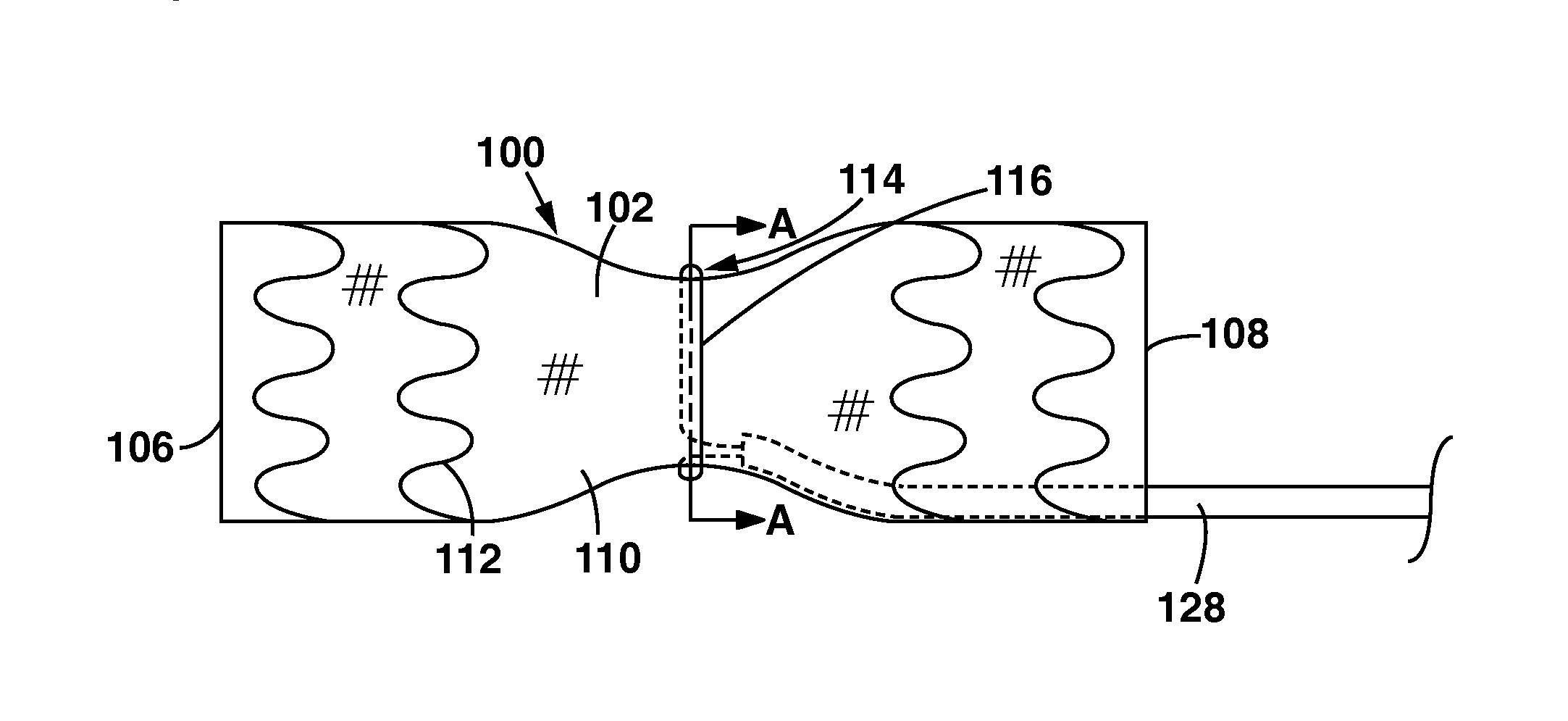
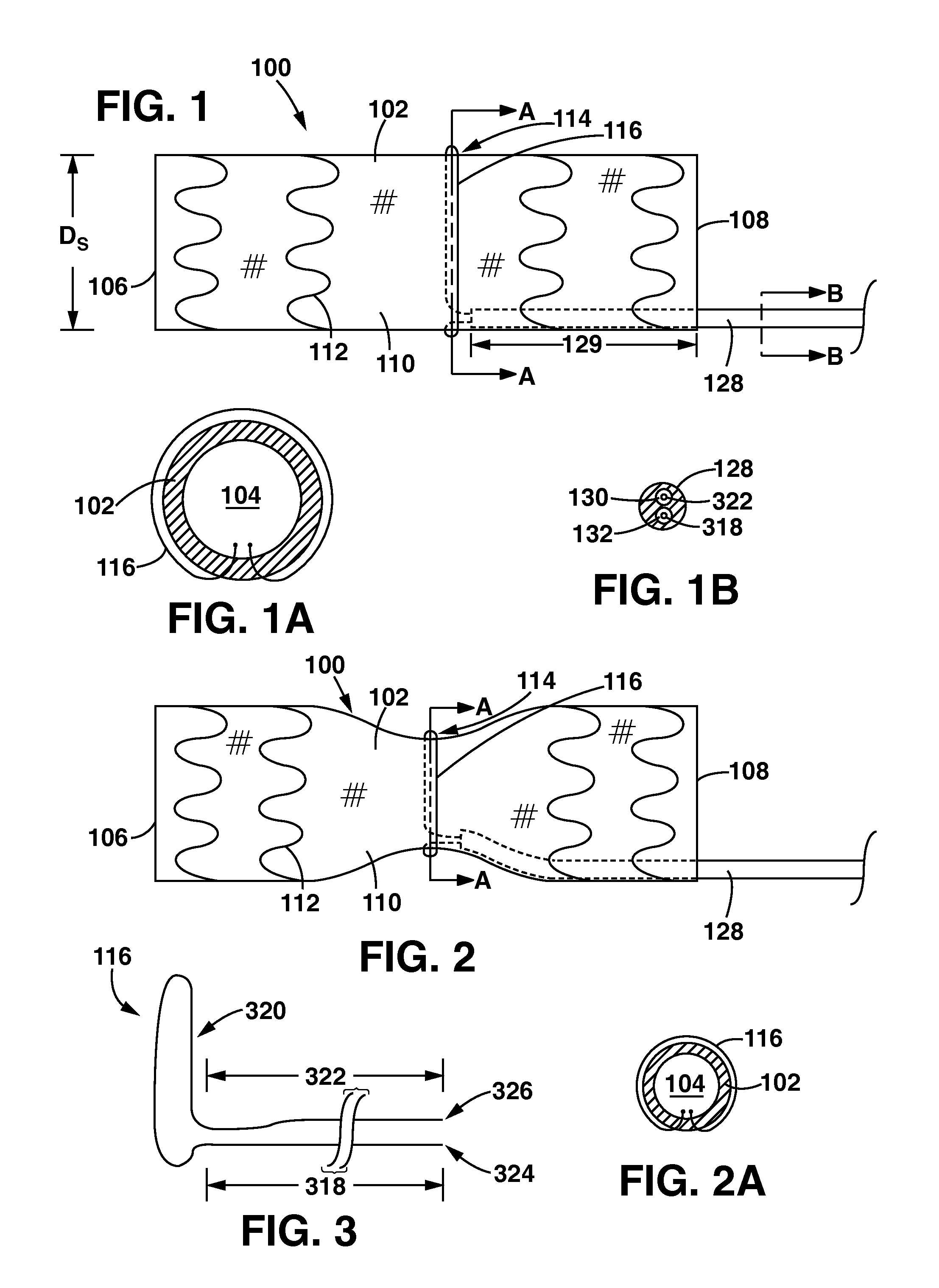
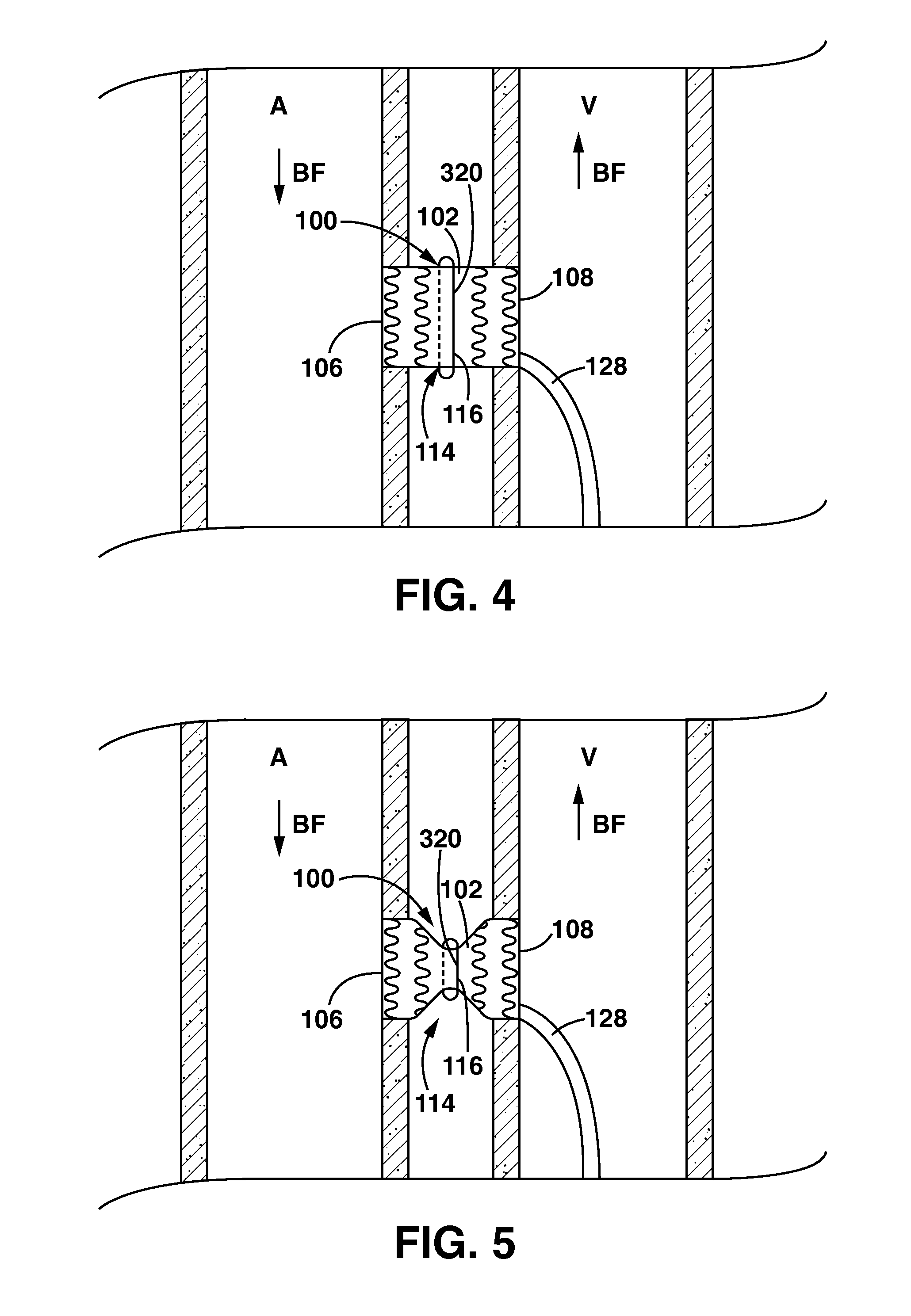
[0023]Specific embodiments of the present invention are now described with reference to the figures, wherein like reference numbers indicate identical or functionally similar elements. The terms “distal” and “proximal” are used in the following description with respect to a position or direction relative to the treating clinician. “Distal” or “distally” are a position distant from or in a direction away from the clinician. “Proximal” and “proximally” are a position near or in a direction toward the clinician. In addition, the term “self-expanding” is used in the following description with respect to components that have a mechanical memory to return to an expanded deployed configuration from a compressed or constricted delivery configuration. Non-exhaustive exemplary materials that may be used to form self-expanding components include stainless steel, a pseudo-elastic metal such as a nickel titanium alloy (nitinol), a polymer, or a so-called superalloy, which may have a base metal o...


PUM


Abstract

An arteriovenous shunt assembly including a shunt and a pull wire operated flow control mechanism. The shunt has a tubular body that defines a fluid passageway between a first end and a second end thereof The pull wire mechanism includes a portion disposed around the tubular shunt in at least one loop. The at least one loop may be selectively tightened or loosened remotely from the shunt to regulate the rate of blood flow through the tubular shunt.

Description

FIELD OF THE INVENTION[0001]The invention relates to an arteriovenous (AV) shunt assembly having a flow control mechanism for regulating flow there through.BACKGROUND OF THE INVENTION[0002]In modern medicine there are numerous treatment situations in which it is desirable to create shunts or flow-through connections between blood vessels and / or other anatomical structures of the body. Such treatments include, for example, hemodialysis, hemofiltration, hemodiafiltration, plasmapheresis, and extracorporeal membrane oxygenation (ECMO). In many cases, open surgical techniques have been used to form anatomic connections or fistulas between adjacent vessels of body structures. More recently, percutaneous catheter-based techniques and devices have been developed for creating channels or passageways between adjacent vessels or anatomical structures.[0003]In addition to the above-listed treatments, arteriovenous (AV) shunt devices have been proposed for treating chronic obstructive pulmonary...

Claims


Application Information

Patent Timeline
Patent Type & Authority Patents(United States)
IPC IPC(8): A61M5/00A61F2/07A61M39/28A61M5/168A61B17/11A61F5/00
CPCA61M39/28A61F2/07A61M5/16813A61B17/11A61F2002/072A61F5/004A61B2017/1139A61B2017/1107
Inventor GALLAGHER, JOHNMCCAFFREY, GERRY
Owner MEDTRONIC VASCULAR INC
Why Eureka
Try Eureka