Fluid-filled type vibration damping device

a technology of vibration damping device and fluid chamber, which is applied in the direction of shock absorbers, machine supports, mechanical equipment, etc., can solve the problems of risk of being less durable and reliable, and the effect of effective vibration damping action

Active Publication Date: 2015-06-30
SUMITOMO RIKO CO LTD
View PDF34 Cites 4 Cited by
  • Summary
  • Abstract
  • Description
  • Claims
  • Application Information

AI Technical Summary

Benefits of technology

[0059]According to the present invention, variation of the tuning frequency of the orifice passage is carried out through adjustment of the insertion or intrusion distance of the inside orifice member into the outside orifice member. Thus, effective vibration damping action of several types of vibration with different frequencies may be achieved with better dependability and durability.

Problems solved by technology

However, while the orifice passage affords excellent vibration damping action of vibration having the frequency to which it has been pre-tuned, in the case of vibration of high frequency above the tuning frequency, extremely high dynamic spring may arise due to antiresonance, and the resultant appreciable drop in vibration damping capability can sometimes be a problem.
Where the drive transmission member is arranged passing through the fluid chambers in this way, the sealing structure for the fluid chamber of necessity becomes more complicated, posing a risk of being less durable and dependable; and the mount manufacturing operation, e.g. the fluid sealing operation during attachment of the drive transmission member, is considerably more difficult, posing a number of unresolved issues in terms of commercial viability.
However, in structures for providing the orifice passage with variable cross-sectional area as disclosed in Patent Citations 2 and 3, the gap extends in the circumferential direction, so making the cross-sectional area of the orifice passage smaller necessitates making the gap correspondingly narrow, which creates the problem of excessively high fluid flow resistance due to the narrowness of the gap.
Specifically, while it is theoretically possible to set the tuning frequency of the orifice passage to a lower level by constricting the gap, a problem encountered in actual practice is that flow resistance rises to the point that an adequate level of fluid flow is not readily assured, making it difficult to achieve the desired orifice action.
The resultant difficulty of varying the size of gap between the opposing faces in a rapid manner may pose problems in terms of ensuring adequate response speed and levels of drive force.

Method used


Image

  • Fluid-filled type vibration damping device
  • Fluid-filled type vibration damping device
  • Fluid-filled type vibration damping device

Examples


first embodiment

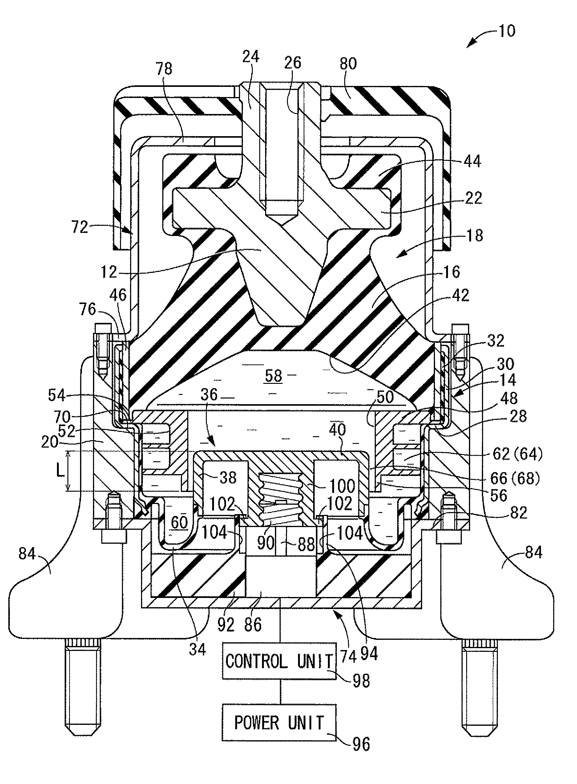
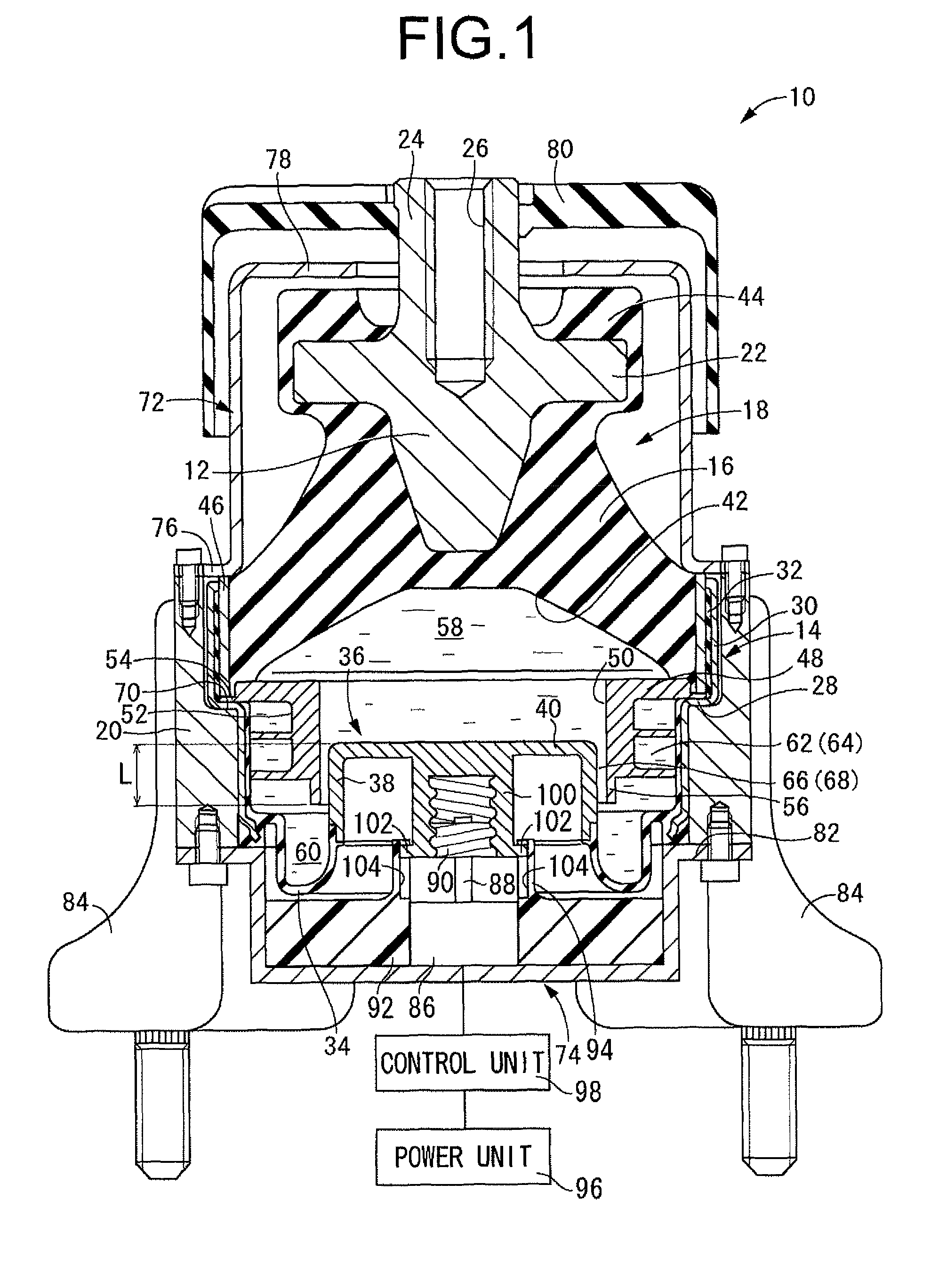
[0074]Referring first to FIG. 1, there is depicted an automotive engine mount 10 as the fluid-filled type vibration damping device according to the present invention. This engine mount 10 has a construction in which a mount assembly 18, composed of a first mounting member 12 and a second mounting member 14 arranged spaced apart in opposition to one another and elastically linked by a main rubber elastic body 16 interposed between them, fits within a bracket 20. The engine mount 10 is designed to provide vibration damping support of the power unit on the vehicle body by attaching the first mounting member 12 to a power unit (not shown) and attaching the second mounting member 14 to the vehicle body (not shown). In this installed state, the distributed load of the power unit is exerted on the engine mount 10 across the first mounting member 12 and the second mounting member 14 in the direction of center axis of the mount, which is the vertical direction in FIG. 1, thereby inducing the...

second embodiment

[0183]In the preceding second embodiment, a metal mass may be anchored to the moveable rubber film 108 to tune it to the frequency at which the moveable rubber film 108 exhibits elastic resonance (the natural frequency of the moveable rubber film 108).

[0184]In the preceding second embodiment, the second fluid chamber 60 may be replaced by a first equilibrium chamber connecting to the primary fluid chamber 116 through the low-frequency orifice passage 64, and a second equilibrium chamber connecting to the auxiliary fluid chamber 118 through the orifice passage 68.

third embodiment

[0185]In the preceding third embodiment, the second fluid chamber 60 may be replaced by a first equilibrium chamber connecting to the primary fluid chamber 132 through the low-frequency orifice passage 64, and a second equilibrium chamber connecting to the auxiliary fluid chamber 134 through the orifice passage 68.

[0186]In the present invention, the actuator is not limited to an electric motor. Other arrangements in which, for example, the actuator is constituted by a solenoid, or the actuator is constituted by a cam mechanism and an electric motor adapted to drive a cam member making up the cam mechanism could also be employed.

[0187]In the preceding first to eighth embodiments, the rotational drive power of the electric motor 86 may be transmitted to the external thread member 90 via a reduction gear train.

[0188]Whereas the preceding first to eighth embodiments described specific examples of implementation of the present invention in an automotive engine mount, the invention has po...


PUM


Abstract

A fluid-filled type vibration damping device having a first and a second fluid chamber respectively filled with non-compressible fluid and which experience relative pressure fluctuations during vibration input, and provided with an orifice passage through which the first fluid chamber and the second fluid chamber communicate with one another, while being capable of exhibiting better dependability and durability in terms of effective vibration damping action of several types of vibration with different frequencies. In the device, tuning frequency of the orifice passage is varied by varying a passage length of the orifice passage 68 through adjustment of an insertion distance of an inside orifice member into an outside orifice member.

Description

TECHNICAL FIELD[0001]The present invention relates to a vibration damping device such as an engine mount for example; and relates in particular to a fluid-filled type vibration damping device adapted to give rise to vibration damping by utilizing the flow action of a non-compressible fluid filling the interior.BACKGROUND ART[0002]Vibration damping devices designed for installation between components making up a vibration transmission system in order to provide vibration damping linkage and vibration damping support between the components are known in the art. One example is an engine mount for providing vibration damping support of an automotive power unit on the vehicle body.[0003]In the field of automotive engine mounts, a high degree of vibration damping capability is required for improved ride comfort. To meet this need, there have been proposed a number of fluid-filled type vibration damping devices designed to utilize the flow action, such as resonance action, of a non-compres...

Claims


Application Information

Patent Timeline
Patent Type & Authority Patents(United States)
IPC IPC(8): F16F13/26F16F13/10
CPCF16F13/262F16F13/106F16F13/264F16F13/266
Inventor YAMAMOTO, SEIICHIROHASEGAWA, KOICHIHAMADA, MASAAKI
Owner SUMITOMO RIKO CO LTD
Why Eureka
Try Eureka