Measuring apparatus

a technology of measuring apparatus and measuring cylinder, which is applied in the field of measuring cylinders, can solve the problems of irradiation timings that may actually be discrepant, individual differences in pulsed light sources, and age-related deterioration, so as to reduce the discrepancy of emission timings, improve diagnostic image quality, and reduce the effect of artifacts

Inactive Publication Date: 2015-07-07
CANON KK
View PDF14 Cites 4 Cited by
  • Summary
  • Abstract
  • Description
  • Claims
  • Application Information

AI Technical Summary

Benefits of technology

[0012]With the foregoing in view, the present invention provides a technology to decrease a discrepancy of the emission timings of light sources, and decrease the artifacts in the diagnostic image in a measuring apparatus having a plurality of light sources.
[0014]According to the present invention, image quality can be improved by decreasing the discrepancy of emission timings among light sources, and decreasing the artifacts in the diagnostic image.

Problems solved by technology

Pulsed light sources have individual differences and are subject to aged deterioration.
Therefore even if a control signal is transmitted to a plurality of light sources to irradiate a pulsed light at a same timing, the irradiation timings may actually be discrepant.
Therefore in the case of a measuring apparatus which generates a diagnostic image using a photoacoustic wave generated by irradiating a plurality of pulsed lights for a plurality of times, the diagnostic image may be uneven.

Method used


Image

  • Measuring apparatus
  • Measuring apparatus
  • Measuring apparatus

Examples


first example

(General Configuration)

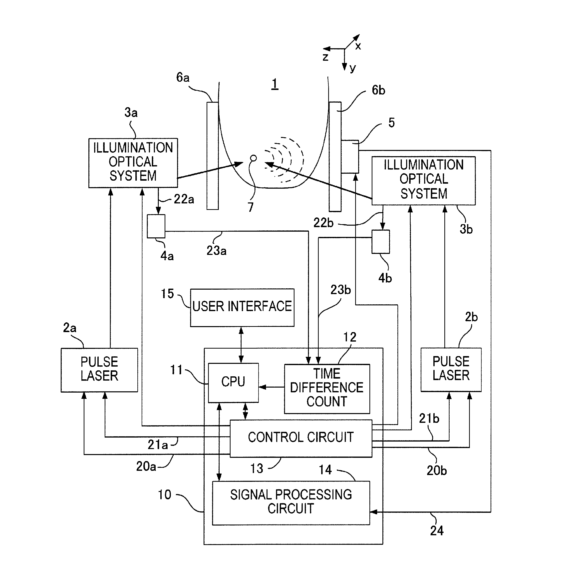
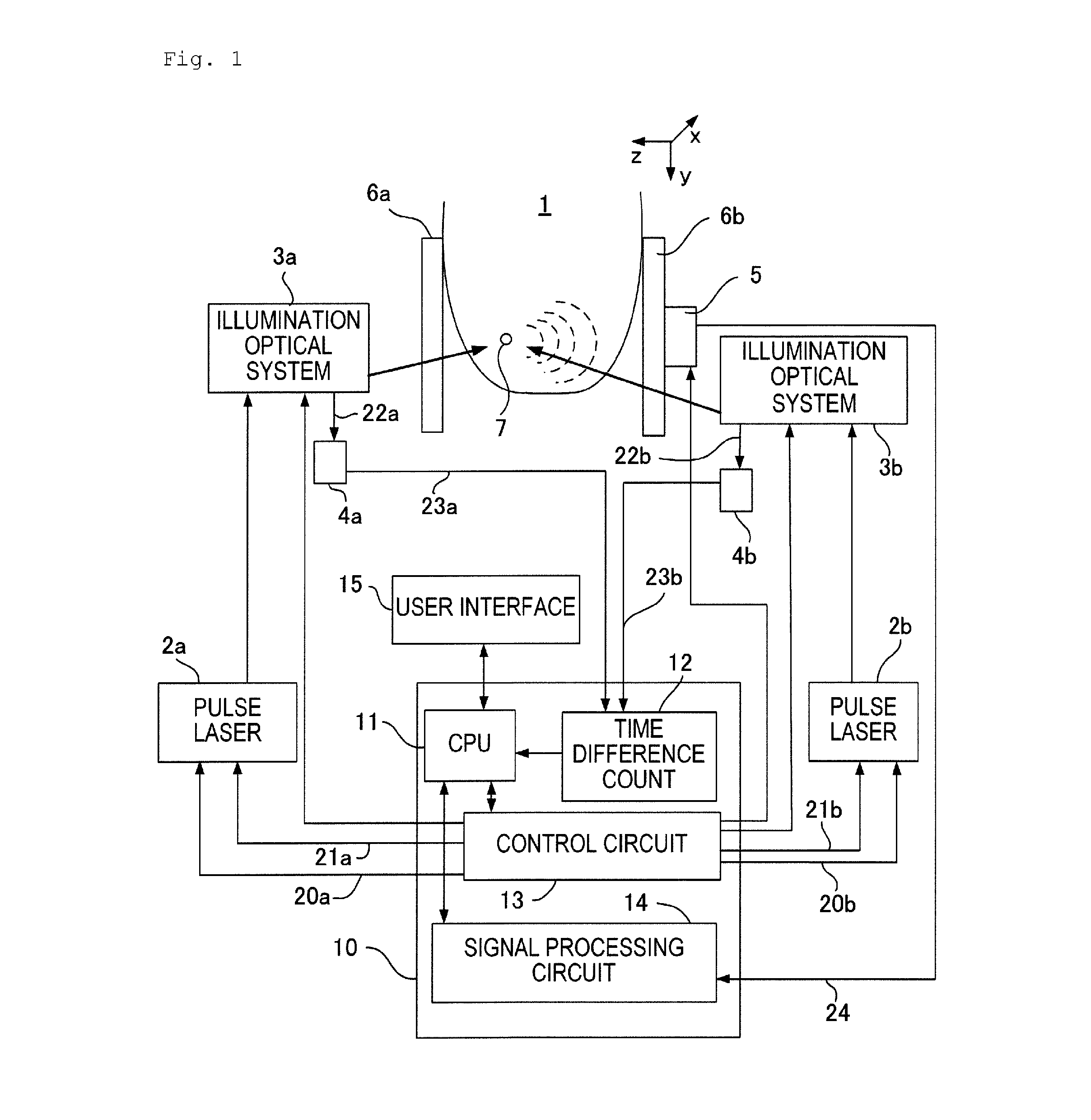
[0048]FIG. 1 is a block diagram depicting a first example of a measuring apparatus according to the present invention. In FIG. 1, 1 is a subject and a part of a body of a subject person. For example, if the measuring apparatus is used for the diagnosis of breast cancer, a breast is the subject. This measuring apparatus has a plurality of (two in this example) pulse laser sources 2a and 2b. Hereafter the pulse laser source 2a is also referred to as a first laser source, and the pulse laser source 2b as a second laser source. The pulse laser sources 2a and 2b are light sources for generating pulsed light, and are constituted by a YAG laser, a titanium-sapphire laser or the like. The pulse laser sources 2a and 2b have a flash lamp as a means for exciting the laser medium inside the pulse laser source. Each pulse laser source 2a and 2b has a Q switch. The flash lamp and the Q switch can be externally controlled electrically. If the Q switch is turned ON after turn...

second example

[0107]Second example of the present invention will be described next. A difference of Second example from first example is that a timing is also adjusted when measuring a subject. This example is for supporting a case when the fluctuation of the emission timing is gradually increasing when pulsed light is irradiated onto the subject, due to the temperature rise inside the pulse laser source.

[0108]Description on the block diagram in FIG. 1 and the control signal generation circuit 30 in FIG. 3 is omitted since both are already described in first example.

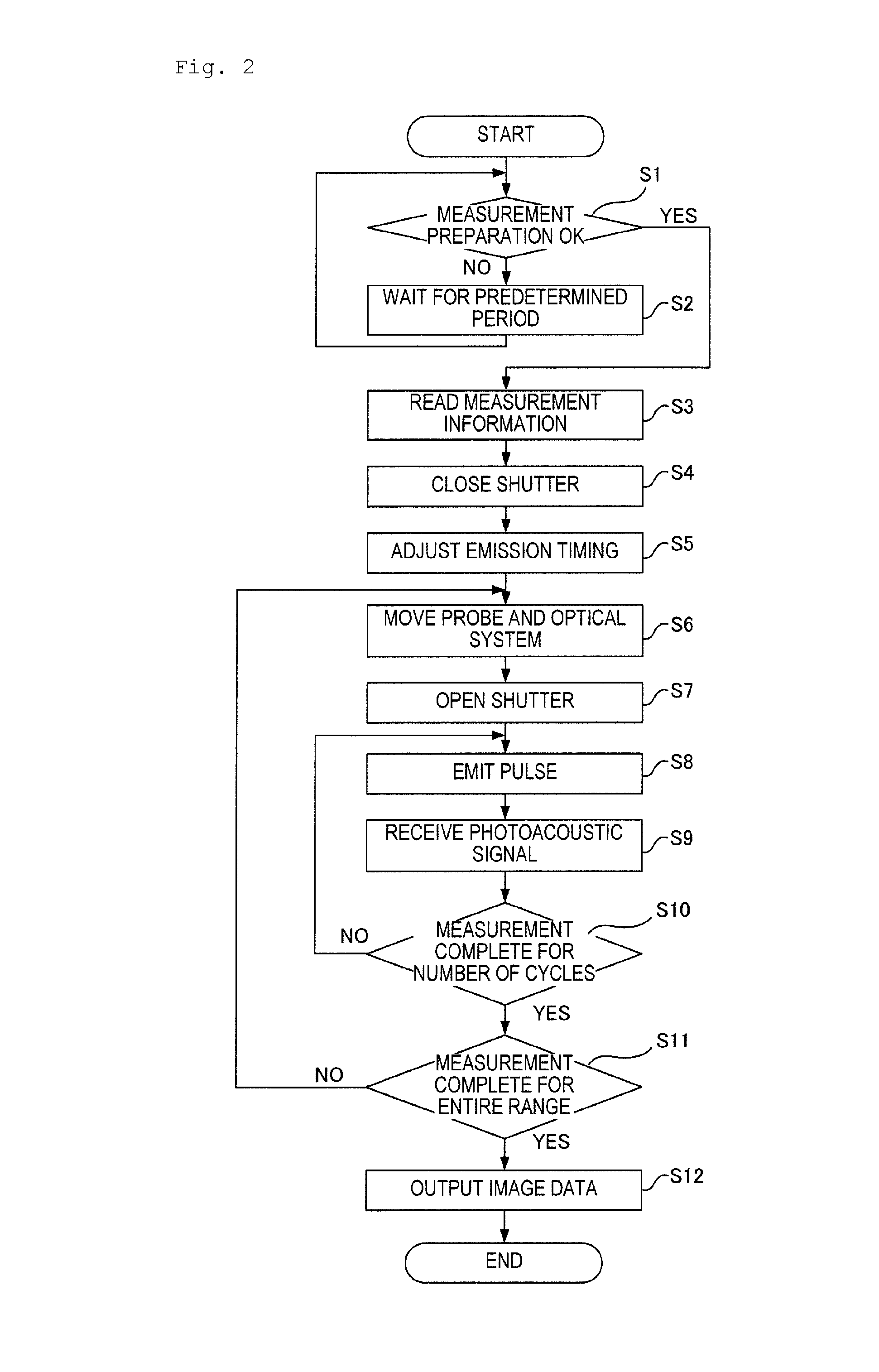
[0109]An operation flow of a measuring apparatus of this example will now be described with reference to FIG. 7. Description on step S30 to step S33, which is the same as step S1 to step S4 in first example, is omitted. It is assumed that the values in the previous measurement are held in the register 31 in the control circuit 13 when step S33 is completed. Description on step S34 to step S36, which is the same as step S6 to step S8 i...

third example

[0113]Third example of the present invention will be described next. A difference of third example from first example is that not only a timing of turning ON the flash lamp of the pulse laser sources, but also the interval from the turning ON the flash lamp to the oscillation of the Q switch is changed. By changing the interval from the lighting of the flash lamp to the oscillation of the Q switch, the quantity of the energy to be stored in the laser medium inside the pulse laser source is changed. This example allows to adjust the pulsed light to be irradiated onto the subject 1. For example, in FIG. 1, a strong photoacoustic wave may be generated from the surface of the plate member 6b in some cases when the quantity of pulsed light from the illumination optical system 3b is too strong. In this case, the photoacoustic wave, not from the subject 1, wraps around the probe 5, which may generate an artifact. A case of decreasing the quantity of pulsed light from the illumination optic...


PUM

PropertyMeasurementUnit
frequencyaaaaaaaaaa
time differenceaaaaaaaaaa
timeaaaaaaaaaa

Abstract

A measuring apparatus includes: laser sources; and a control unit for outputting an excitation start signal that instructs the laser light sources to start excitation, and outputting an oscillation start signal to instruct the laser light sources to start oscillation after a predetermined time has elapsed from the output of the excitation start signal, so as to generate pulsed light from the laser light sources. The laser sources include a first laser source and a second laser source of which preparation time from the start of the excitation to the generation of the pulsed light is longer than that of the first laser source. The control unit sets timing to output the excitation start signal to the first laser source to follow timing to output the excitation start signal to the second laser source according to a difference of the preparation time between the first and second laser sources.

Description

TECHNICAL FIELD[0001]The present invention relates to a measuring apparatus for measuring spectral characteristics inside a biological tissue using a photoacoustic effect.BACKGROUND ART[0002]Many measuring apparatuses, in which a pulsed light is irradiated onto a biological object, a photoacoustic wave generated from inside the biological object is received by a probe, and the forms and functions inside the biological tissue are displayed as images, have been proposed in medical fields. This technology is called “photoacoustic tomography (PAT)”. In such an apparatus, the intensity of the light irradiated into the biological tissue attenuates while propagating inside the biological tissue due to absorption and scattering, hence only very little light reaches the depth of the tissue. As a result, photoacoustic waves are generated inside the biological tissue, and electric signals (photoacoustic signals) converted by the probe become weak. To prevent this, a Q switch is installed in th...

Claims


Application Information

Patent Timeline
Patent Type & Authority Patents(United States)
IPC IPC(8): A61B8/00G01N29/00G01N21/17A61B5/00G01N21/00G01N21/47G01N21/49A61B8/08
CPCG01N21/1702A61B5/0095G01N21/4795A61B5/4312A61B8/485G01N21/49G01N2021/1787G01N2201/0697
Inventor SUZUKI, KOICHI
Owner CANON KK
Why Eureka
Try Eureka