
Method for producing piston rings

Active Publication Date: 2015-07-14
FEDERAL MOGUL BURSCHEID
View PDF24 Cites 1 Cited by
  • Summary
  • Abstract
  • Description
  • Claims
  • Application Information

AI Technical Summary

Benefits of technology

The invention allows for a faster and more cost-effective process for turning the outer contour of piston rings. By combining the rings into one packet on the mandrel, the outer surface of the piston ring can be machined without the need for an outer contour turning work step. The smooth cylinder can also be electro-chrome-plated with minimal current consumption and better layer thickness distribution. Additionally, suitable profile grinding tools can provide the required bearing surface contour without risking damage to the piston ring material.

Problems solved by technology

The external turning work step for producing the desired contour on the outside peripheral surface is extremely time and cost intensive.

Method used


Image

  • Method for producing piston rings
  • Method for producing piston rings

Examples


Embodiment Construction

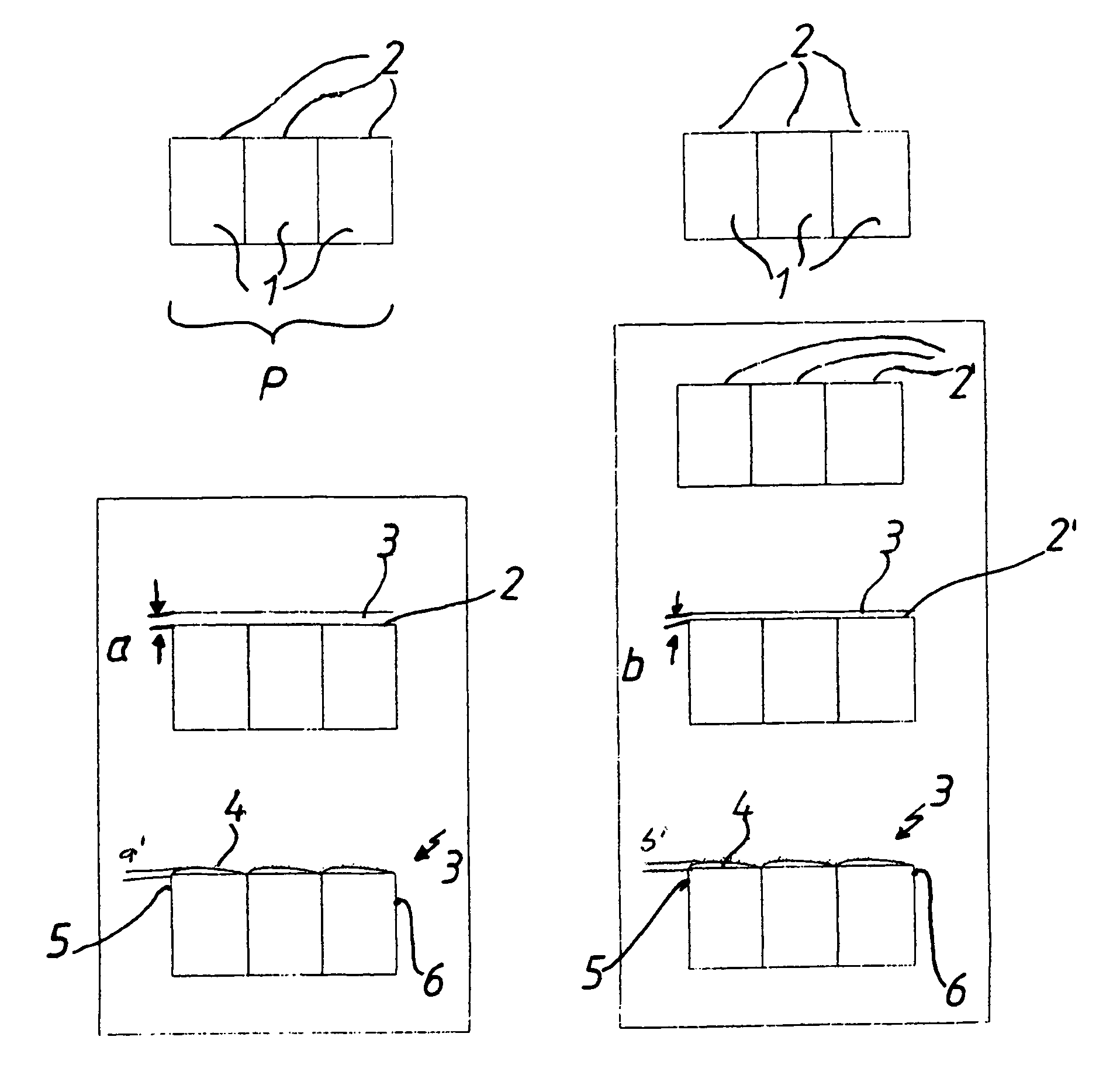
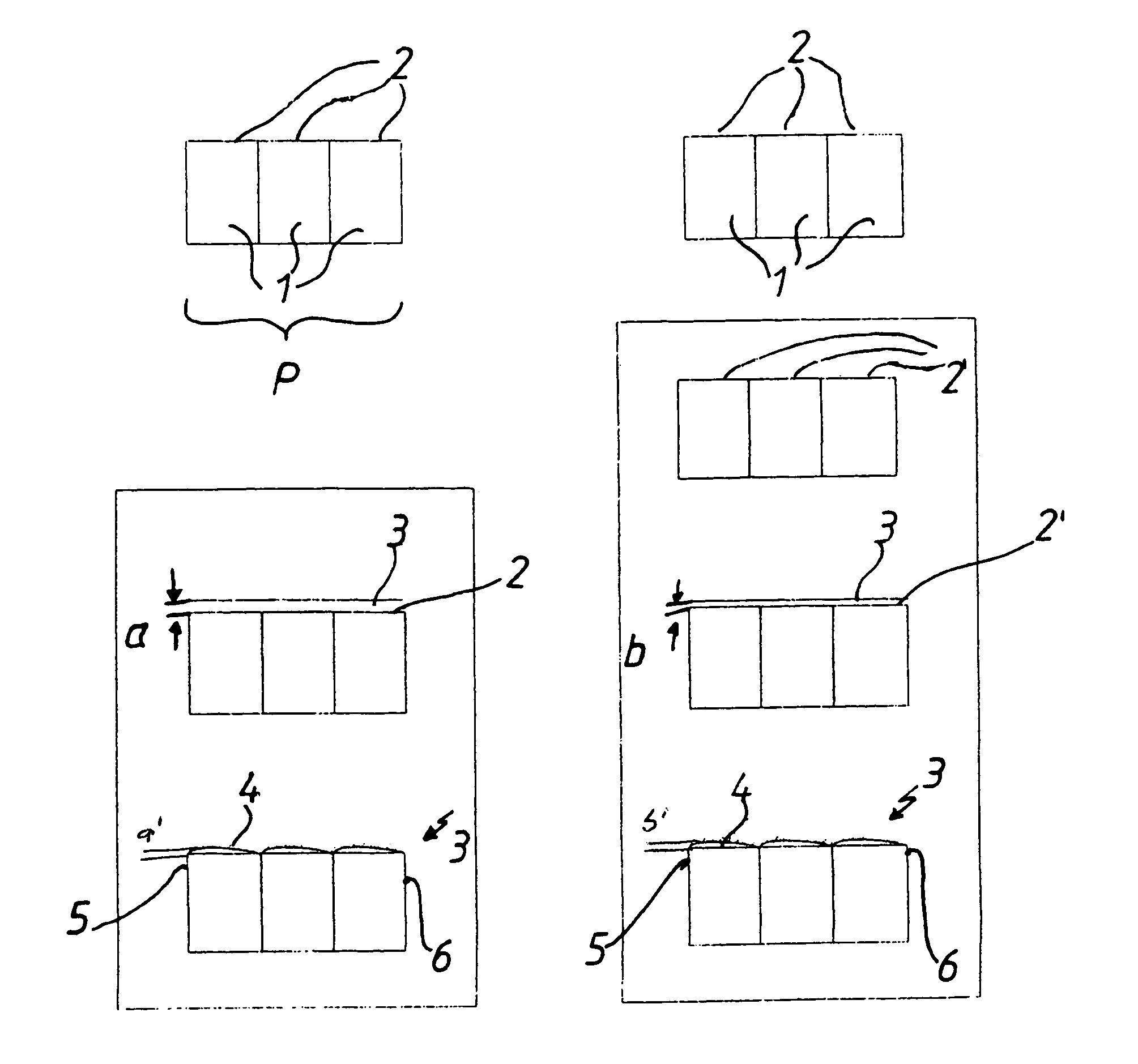
[0021]Two examples for producing piston rings are shown in this single FIGURE—Compression piston rings, in particular. In both examples, base body 1, which is made of cast iron, for example, are combined to form a packet P that is only indicated, and base body 1 is subjected to contour turning, such that this process forms an outer cylindrical peripheral surface 2.

[0022]In the example at left, an electroplated, chrome, wear-resistant layer 3 of predetermined layer thickness a is directly applied to the cylindrical peripheral surface 2. Layer 3 is now the only layer to be machined using a profile grinding tool (not shown) in such a way that it produces a rounded contour 4, which in this example, has a maximum thickness of a′ in one of the bearing surface edge regions 5, whereas the layer thickness for the other bearing surface edge area 6 is provided in minimized form.

[0023]In the example at right, the cylindrical grinding step is performed after the cylindrical contour turning step,...


PUM

PropertyMeasurementUnit
Electrical resistanceaaaaaaaaaa

Abstract

A method for producing piston rings, in particular compression piston rings, in which at least one main element is machined in such a way that a circumferential surface serving as a running surface is provide with a wear-resistant layer of a predeterminable layer thickness, wherein a number of piston ring, in particular compression piston rings, brought together to form an assembly, are machined cylindrically in the region of their circumferential surface, a wear-resistant electrodeposited layer of chrome is applied to the finished machined cylindrical circumferential surface, so that the wear-resistant layer has a constant layer thickness within the assembly as a whole, and subsequently the layer is machined in such a way as to produce a running surface that has a region of maximum layer thickness and at least one region of minimum layer thickness.

Description

BACKGROUND OF THE INVENTION[0001]1. Technical Field[0002]This invention concerns a method for machining piston rings—compression piston rings in particular—that are in accordance with a mate-forming part of the initial patent claim[0003]2. Related Art[0004]In many cases, piston rings are produced in such a way that they are cylindrically machined on their outer peripheral surface. External turning is subsequently used to produce a contour that will be needed at a later point; this contour is referred to as a bearing surface contour. A wear-resistant layer is then applied to this above-mentioned bearing surface contour—this could, for example, be a chromium layer—which is reflected on the machined contour and on the one that follows. The final running surface geometry is created by cylindrical lapping. In order to execute this work step within a reasonable period of time and with the correct convexity, the contact surface must already have a contour at this point that is very close t...

Claims


Application Information

Patent Timeline
IPC IPC(8): B23P15/06
CPCB23P15/06B23P13/02B23P17/02F16J9/26
Inventor BARENREUTER, DIRKKELLNER, MARKUS
Owner FEDERAL MOGUL BURSCHEID
Learn More