Audio beamforming

a beamforming and audio technology, applied in the direction of transducer details, electrical transducers, signal processing, etc., can solve the problems of many beamforming algorithms, beamwidth deterioration, and inability to provide sufficient directivity, so as to improve the performance, improve the effect of facilitating the adaptation to the current audio environment and improve the performan

Active Publication Date: 2015-07-14
MEDIATEK INC
View PDF5 Cites 1 Cited by
  • Summary
  • Abstract
  • Description
  • Claims
  • Application Information

AI Technical Summary

Benefits of technology

[0011]The invention may allow improved performance. In particular, an improved and / or facilitated adaptation to a current audio environment can be achieved. The invention may allow a beamforming approach which provides high performance for both directional point interference cancellation and for diffuse noise attenuation. The approach is particularly suitable for, and may provide particularly advantageous performance for, systems wherein the wavelength of the audio signals may be substantially larger than the size of the microphone array.
[0044]This may provide particularly advantageous performance and / or facilitated implementation and / or operation.

Problems solved by technology

However, when the wavelength of the sound of interest is much larger than the size of the array, many beamforming algorithms, such as additive delay-and-sum beamforming algorithms, are not able to provide sufficient directivity as the beamwidth deteriorates substantially for such wavelengths.
However, although this may improve the directivity, it is also known that this is achieved at the expense of robustness, such as increased sensitivity to white (sensor) noise and an increased sensitivity to mismatches in microphones characteristics.
However, although this approach provides improved performance in many scenarios, it provides non optimal performance in some practical scenarios.
It also tends to require relatively complex and resource demanding processing.

Method used


Image

  • Audio beamforming
  • Audio beamforming
  • Audio beamforming

Examples


Embodiment Construction

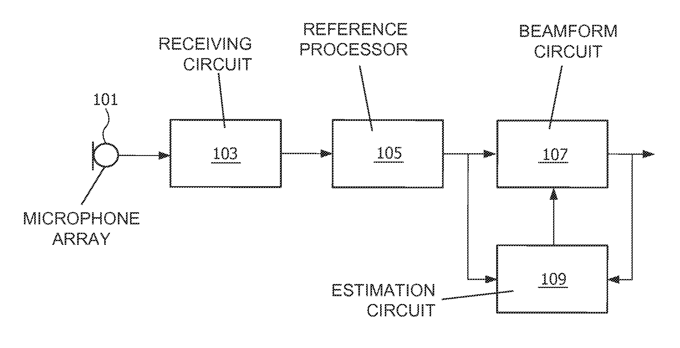
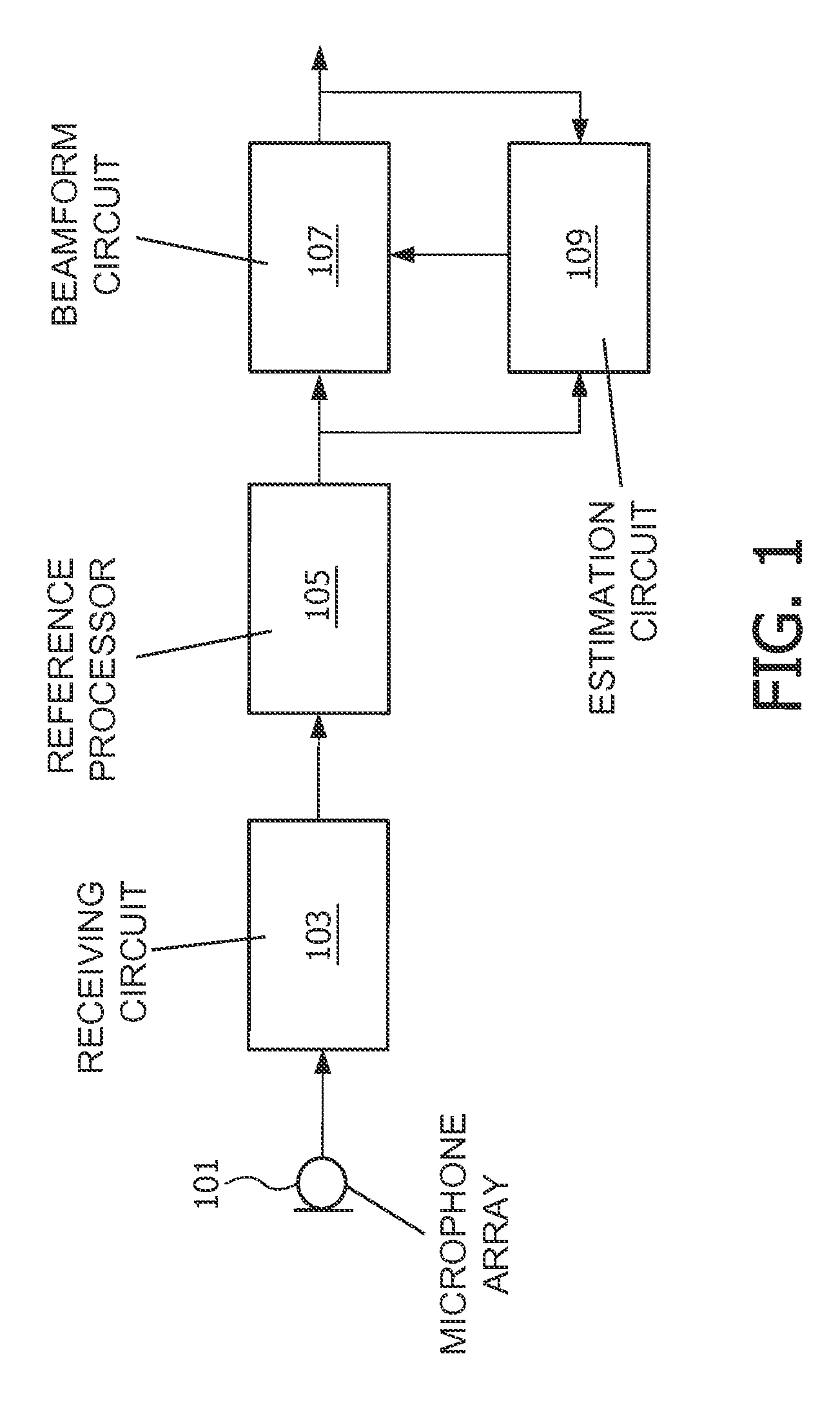
[0056]FIG. 1 illustrates an example of a system for capturing audio with an adaptable directional characteristic. The system processes signals from a plurality of microphones to generate a suitable desired beam pattern. The processing is specifically adapted such that the generated output signal has substantially improved noise and interference characteristics. The system provides for a joint improvement in both single point interference and diffuse noise performance. The system is furthermore suitable for use in scenarios wherein the wavelength of the signals is substantially longer than the dimensions of the microphone array, i.e. than the distances between the microphones.

[0057]The system processes the received microphone signals to generate a set of constant non-adaptable reference beams. These reference beams are then adaptively combined to generate a desired beam pattern. The combination is adapted such that the resulting beam form is adapted to cancel or substantially attenua...


PUM


Abstract

An audio beamforming apparatus includes a receiving circuit (103) which receives signals from an at least two-dimensional microphone array (101). A reference circuit (105) generates reference beams and a combining circuit (107) generates an output signal corresponding to a desired beam pattern by combining the reference beams. An estimation circuit (109) generates a direction estimate by determining angles corresponding to local minima for a power measure of the output signal in at least a first and respectively second angle interval. The direction estimate is generated by selecting one of the angles. The combining circuit (107) determines combination parameters to provide a notch in an angle corresponding to the direction estimate and a maximization of a directivity cost measure where the directivity cost measure is indicative of a ratio between a gain in the first direction and an energy averaged gain.

Description

FIELD OF THE INVENTION[0001]The invention relates to audio beamforming and in particular, but not exclusively, to audio beamforming using microphone arrays substantially smaller than the wavelength of the audio signals being beamformed.BACKGROUND OF THE INVENTION[0002]Advanced processing of audio signals has become increasingly important in many areas including e.g. telecommunication, content distribution etc. For example, in some applications, such as hands-free communication and voice control systems, complex processing of inputs from a plurality of microphones has been used to provide a configurable directional sensitivity for a microphone array comprising the microphones. Specifically, the processing of signals from a microphone array can generate an audio beam with a direction that can be changed simply by changing the characteristics of the combination of the individual microphone signals.[0003]Typically, beam form algorithms seek to attenuate interferers while providing a hig...

Claims


Application Information

Patent Timeline
Patent Type & Authority Patents(United States)
IPC IPC(8): H04R29/00H04R3/00
CPCH04R3/005H04R2201/401H04R2430/25
Inventor DERKX, RENE MARTINUS MARIA
Owner MEDIATEK INC
Why Eureka
Try Eureka