Supercharge Your Innovation With Domain-Expert AI Agents!

Spherical annular seal member

a technology of annular seals and seals, applied in the direction of cable terminations, machines/engines, mechanical equipment, etc., can solve the problems of deteriorating compartment quietness in some cases, large stress applied to the exhaust system members, etc., to improve the heat resistance of the expanded graphite itself, reduce the oxidative wear of the heat-resistant material at a high temperature, and increase the heat resistan

Active Publication Date: 2015-07-28
OILES CORP
View PDF15 Cites 2 Cited by
  • Summary
  • Abstract
  • Description
  • Claims
  • Application Information

AI Technical Summary

Benefits of technology

The solution significantly reduces oxidative wear and weight loss at high temperatures, improving the seal member's heat resistance and sealing performance, while maintaining structural integrity and reducing gas leakage.

Problems solved by technology

Particularly in the case of a high-speed rotation and high-output engine, the stress applied to the exhaust system members becomes quite large.
Accordingly, the exhaust system members have a possibility of bringing about a fatigue failure, and the engine vibration can cause the exhaust system members to resonate, thereby deteriorating compartment quietness in some cases.

Method used


Image

  • Spherical annular seal member
  • Spherical annular seal member
  • Spherical annular seal member

Examples


examples

[0074]Next, the present invention will be described in detail in accordance with examples; however, it should be noted that the present invention is not limited to these examples.

examples 1 to 6

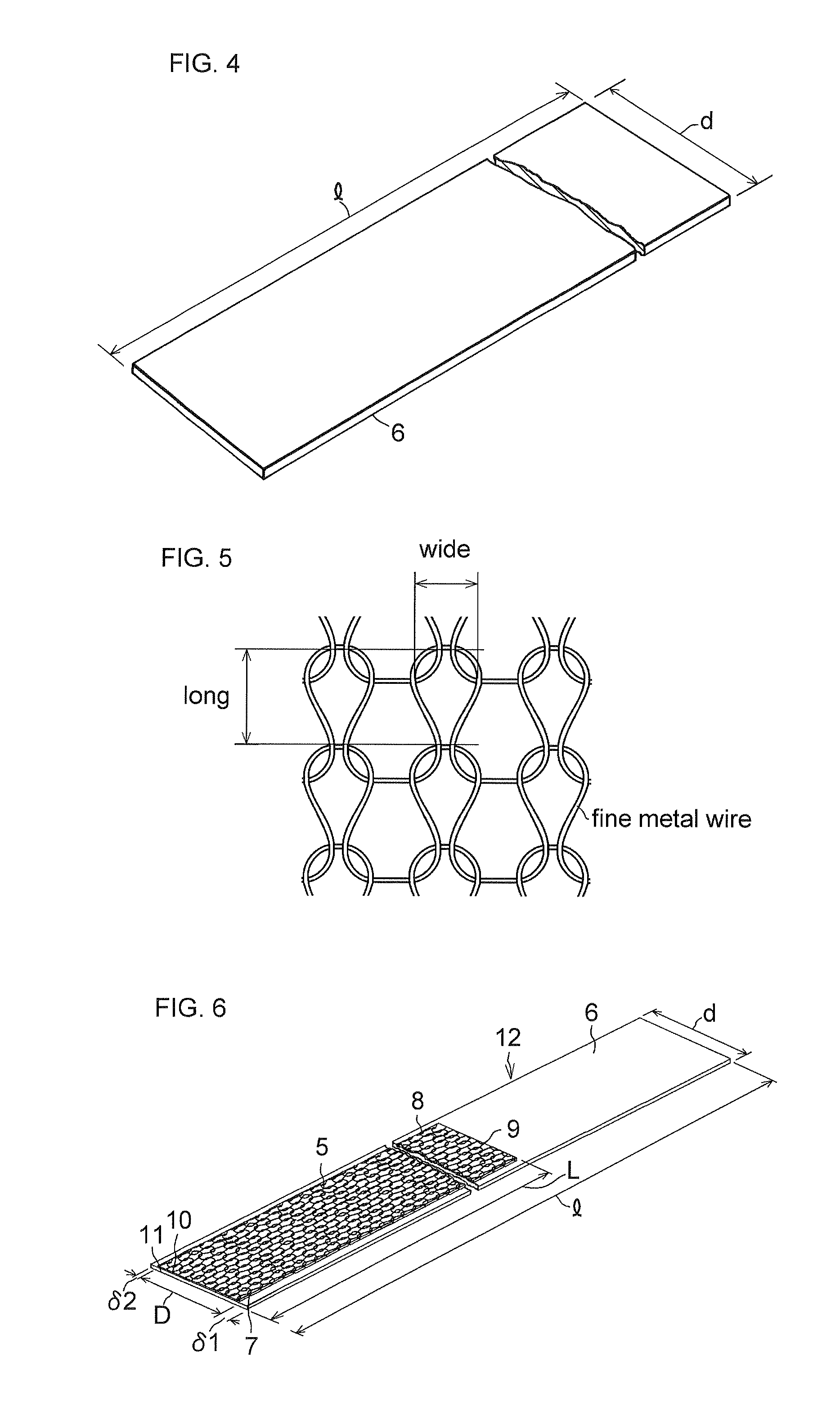
[0075]By using one austenitic stainless steel wire (SUS 304) having a wire diameter of 0.28 mm as a fine metal wire, a cylindrical knitted metal wire net whose mesh size was 4 mm long and 5 mm wide was fabricated and was passed between a pair of rollers to form a belt-shaped metal wire net. This metal wire net was used as the reinforcing member for the spherical annular base member.

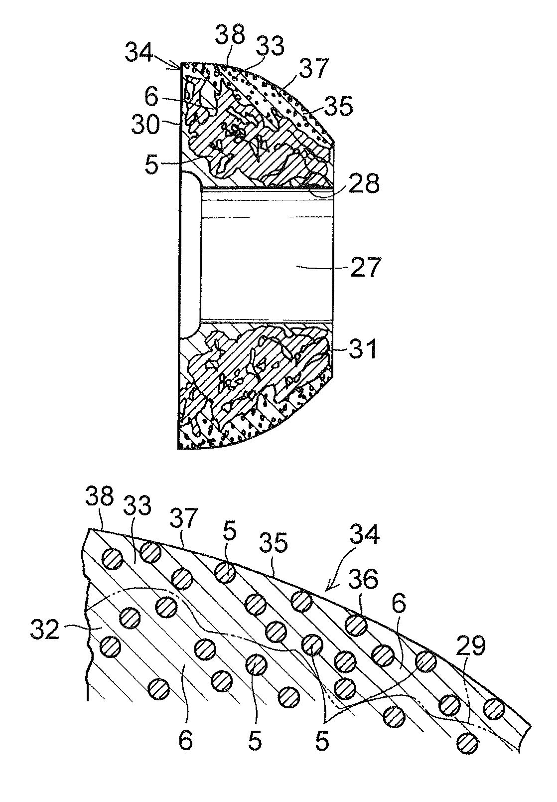
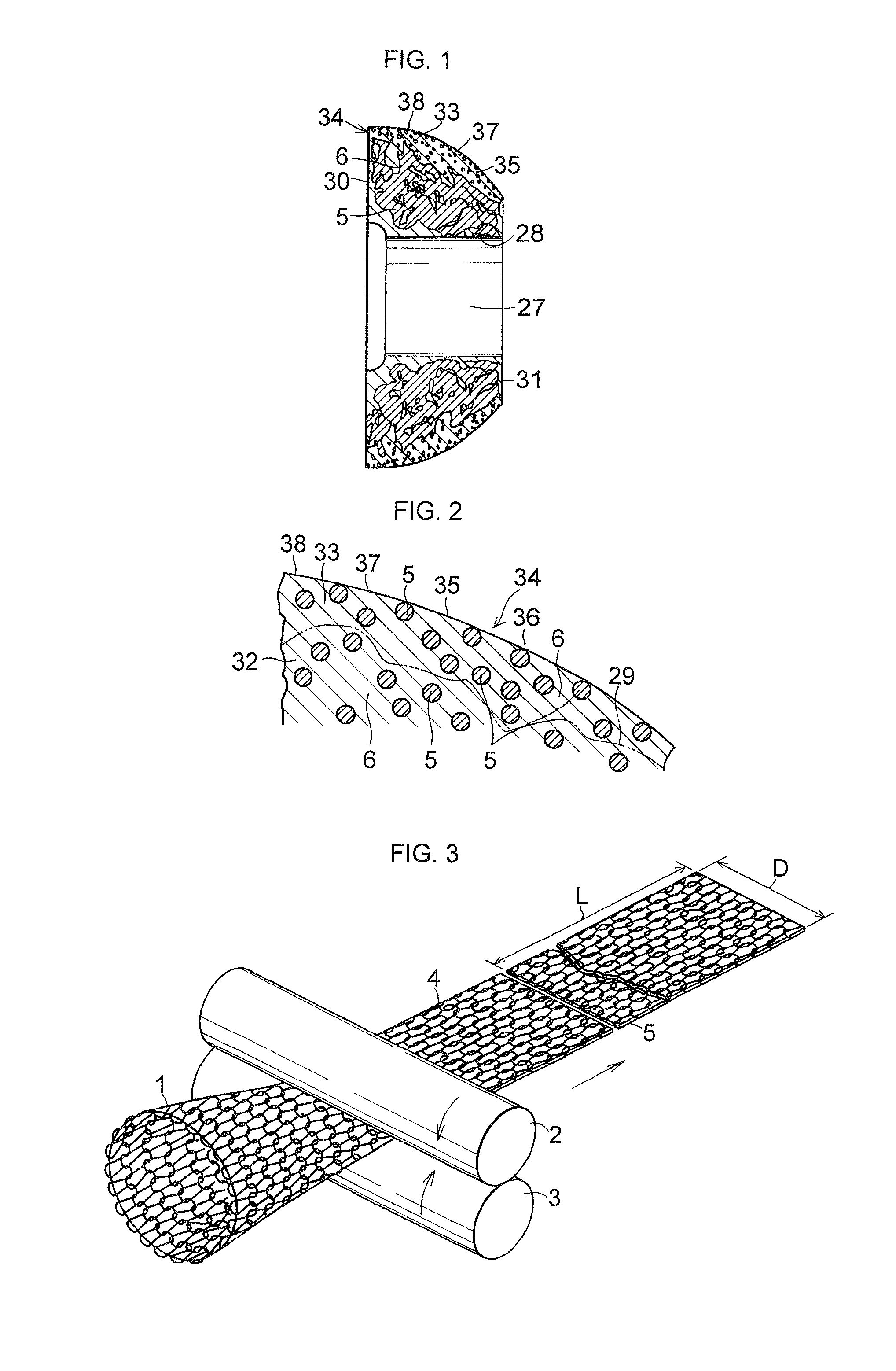
[0076]As the heat-resistant material, an expanded graphite sheet was used in which 0.5 to 12.0% aluminum primary phosphate by mass as a phosphate was contained in expanded graphite whose ash content was 0.01% by mass and whose graphite content was 99.99% by mass, the expanded graphite sheet having a density of 1.12 Mg / m3 and a thickness of 0.38 mm. After the heat-resistant material was convoluted by a one-circumference portion, the reinforcing member was superposed with the heat-resistant material placed on the inner side, and the superposed assembly thereof was convoluted, thereby preparing a tubular bas...

examples 7 to 9

[0082]As the reinforcing member, a reinforcing member for a spherical annular base member and a reinforcing member for an outer layer which were similar to those of the above-described Example 1 were used.

[0083]As the heat-resistant material, an expanded graphite sheet was used in which 1.0 to 8.0% aluminum primary phosphate by mass as a phosphate and 0.5% phosphorus pentoxide by mass were contained in expanded graphite with an ash content of 0.1% by mass and a graphite content of 99.9% by mass, and which had a density of 1.12 Mg / m3 and a thickness of 0.38 mm. Then, the following spherical annular seal members were fabricated by using a method similar to that of the above-described Example 1. The spherical annular base member was constructed so as to be provided with structural integrity as the heat-resistant material and the reinforcing member for the spherical annular base member made from the metal wire net were compressed and intertwined with each other. The spherical annular ba...


PUM


Abstract

A spherical annular seal member 34 includes a spherical annular base member 32 defined by a cylindrical inner surface 28, a partially convex spherical surface 29, and annular end faces 30, 31, as well as an outer layer 33 formed integrally on the partially convex spherical surface 29. The spherical annular base member 32 includes a reinforcing member 5 made from a metal wire net 4 and a heat-resistant material 6 containing expanded graphite and a phosphate and integrated with the reinforcing member 5 in mixed form, and the outer layer includes the heat-resistant material 6 containing the expanded graphite and the phosphate and the reinforcing member 5 made from the metal wire net 4 integrated with the heat-resistant material 6 in mixed form, the expanded graphite in the heat-resistant material 6 having an ash content of not more than 0.1% by mass and a graphite content of not less than 99.7% by mass.

Description

[0001]This application is the U.S. national phase of International Application No. PCT / JP2011 / 004272 filed 28 Jul. 2011 which designated the U.S. and claims priority to JP 2010-184406 filed 19 Aug. 2010, and JP 2010-223824 filed 1 Oct. 2010, the entire contents of each of which are hereby incorporated by reference.TECHNICAL FIELD[0002]The present invention relates to a spherical annular seal member which is suitably used in a spherical pipe joint for an automobile exhaust pipe.BACKGROUND ART[0003]FIG. 15 shows one embodiment of an exhaust passage of an automobile engine, exhaust gases generated in the respective cylinders (not shown) of the engine are gathered in an exhaust manifold catalyst converter 600 and are sent to a sub muffler 603 through an exhaust pipe 601 and an exhaust pipe 602. The exhaust gases which passed through this sub muffler 603 are further sent to a muffler 606 through an exhaust pipe 604 and an exhaust pipe 605, and are released to the atmosphere through this ...

Claims


Application Information

Patent Timeline
Patent Type & Authority Patents(United States)
IPC IPC(8): F16J15/12F16L23/18F01N13/18F16J15/08
CPCF16L23/18F01N13/1827F16J15/0812F16J15/126
Inventor KAIDA, HIDETOSHIKUROSE, KOUHEI
Owner OILES CORP
Features
  • R&D
  • Intellectual Property
  • Life Sciences
  • Materials
  • Tech Scout
  • Unparalleled Data Quality
  • Higher Quality Content
  • 60% Fewer Hallucinations
Learn More