Double pipe type heat exchanger and method for manufacturing the same

a heat exchanger and double pipe technology, applied in the direction of heat exchange apparatus safety devices, lighting and heating equipment, tubular elements, etc., can solve the problems of reducing heat exchange efficiency, generating gap g, and remarkable reduction of heat exchange efficiency, so as to enhance the performance of heat exchanger and efficiently exchange heat , to prevent the inner pipe from moving reliably

Active Publication Date: 2015-07-28
HANON SYST
View PDF28 Cites 20 Cited by
  • Summary
  • Abstract
  • Description
  • Claims
  • Application Information

AI Technical Summary

Benefits of technology

[0011]Another object of the present invention is to provide a double pipe type heat exchanger capable of increasing the time of heat exchange between a fluid flowing along a first flow path defined within an inner pipe and a fluid flowing along a second flow path defined between an inner pipe and an outer pipe, and a method for manufacturing the same.
[0031]By preventing the frictional contact between the inner pipe and the outer pipe, it is possible to prevent generation of contact noises and contact wear in the inner pipe and the outer pipe. This makes it possible to enhance the durability of the heat exchanger and to prolong the lifespan thereof.

Problems solved by technology

However, the conventional double pipe type heat exchanger has a drawback in that a gap G is generated between the inner pipe 10 and the outer pipe 20 due to the assembling tolerance.
This may reduce the heat exchange efficiency and may cause the inner pipe 10 and the outer pipe 20 to make frictional contact with each other.
The existence of this gap G poses a problem in that the second fluid introduced into the second flow path flows along a straight line.
The reduction of the heat exchange time between the first fluid and the second fluid leads to a remarkable reduction of the heat exchange efficiency, which in turn significantly reduce the performance of the heat exchanger.
Another problem of the conventional double pipe type heat exchanger resides in that the gas G existing between the inner pipe 10 and the outer pipe 20 allows the inner pipe 10 to move within the outer pipe 20.
The contact wear of the inner pipe 10 and the outer pipe 20 may significantly reduce the durability of the heat exchanger, thereby shortening the lifespan of the heat exchanger.

Method used


Image

  • Double pipe type heat exchanger and method for manufacturing the same
  • Double pipe type heat exchanger and method for manufacturing the same
  • Double pipe type heat exchanger and method for manufacturing the same

Examples


Embodiment Construction

[0041]Certain preferred embodiments of a double pipe type heat exchanger in accordance with the present invention and a method for manufacturing the same will now be described in detail with reference to the accompanying drawings. The same reference symbols as used in describing the prior art will be used to designate the same elements.

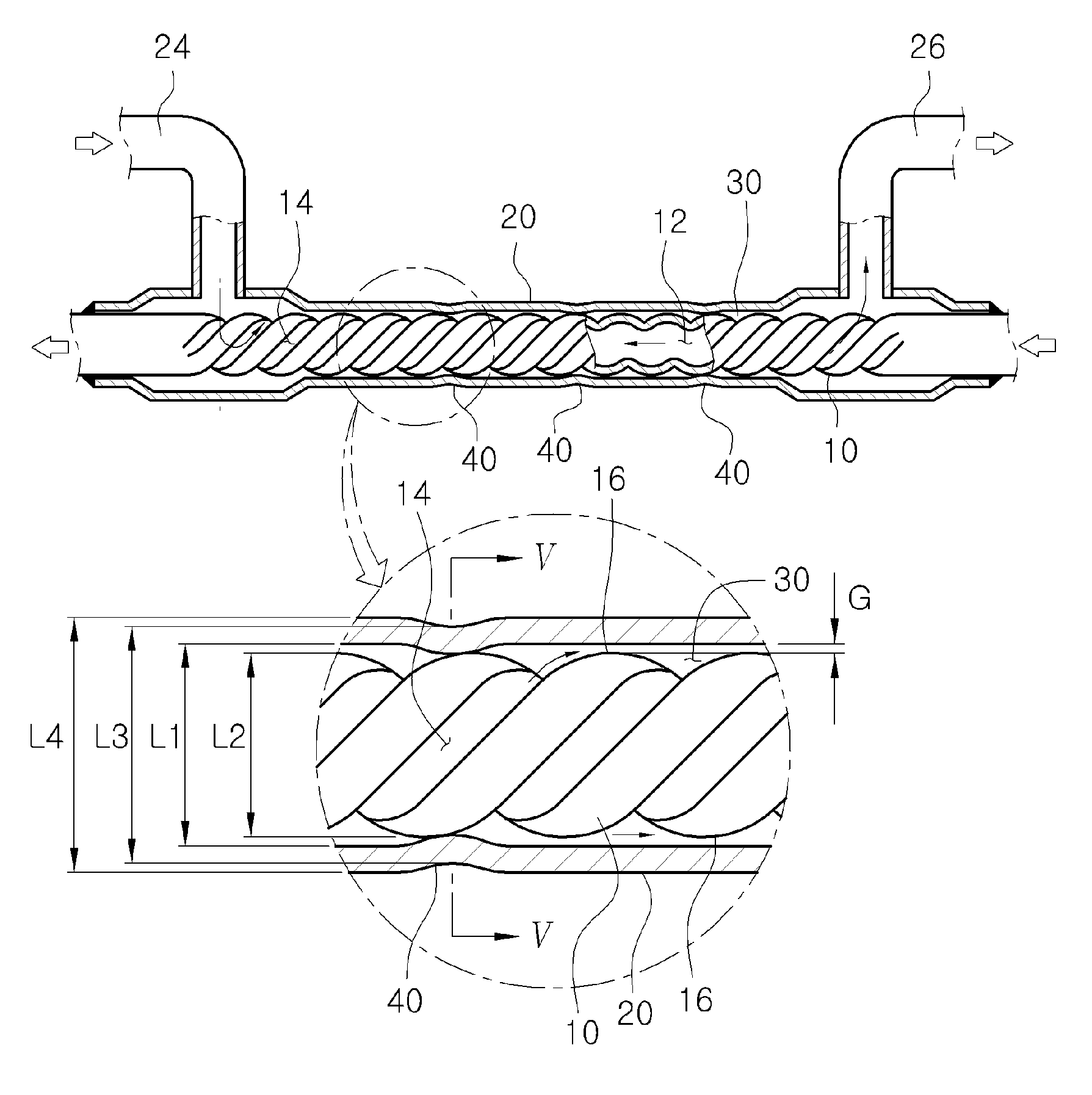
[0042]Referring to FIGS. 3 through 5, the double pipe type heat exchanger in accordance with the present invention includes an inner pipe 10 and an outer pipe 20 arranged to surround the inner pipe 10. The inner pipe 10 is provided with a first flow path 12 defined therein. A first fluid flows along the first flow path 12.

[0043]Spiral grooves 14 are formed on the outer circumferential surface of the inner pipe 10. The spiral grooves 14 extend spirally along the outer circumferential surface of the inner pipe 10. The spiral grooves 14 are formed by, e.g., pressing the outer circumferential surface of the inner pipe 10 with a rolling tool (not shown).

[0...


PUM

PropertyMeasurementUnit
diameteraaaaaaaaaa
temperatureaaaaaaaaaa
heat exchange efficiencyaaaaaaaaaa

Abstract

A double pipe type heat exchanger includes an inner pipe having a first flow path defined therein and an outer pipe arranged around the inner pipe to define a second flow path between the inner pipe and the outer pipe. The inner pipe includes a spiral groove formed on an outer circumferential surface of the inner pipe to extend along a longitudinal direction of the inner pipe. The outer pipe includes a reduced diameter portion protruding inwardly so that the inner surface of the outer pipe is intermittently contacted with the outer circumferential surface of the inner pipe.

Description

FIELD OF THE INVENTION[0001]The present invention relates to a double pipe type heat exchanger and a method for manufacturing the same and, more particularly, to a double pipe type heat exchanger capable of increasing the efficiency of heat exchange between fluids and capable of preventing frictional contact between an inner pipe and an outer pipe and occurrence of contact noises and contact wear and a method of manufacturing the same.BACKGROUND OF THE INVENTION[0002]An air-conditioning system for motor vehicles is provided with various kinds of heat exchangers, e.g., a double pipe type heat exchanger. As shown in FIGS. 1 and 2, a conventional double pipe type heat exchanger includes an inner pipe 10 and an outer pipe 20. The inner pipe 10 is provided with a first flow path 12 through which a first fluid flows. The outer pipe 20 is arranged outside the inner pipe 10 so that a second flow path 30 can be defined between the outer circumferential surface of the inner pipe 10 and the in...

Claims


Application Information

Patent Timeline
Patent Type & Authority Patents(United States)
IPC IPC(8): F28D7/14F28D7/10F28F1/42B21D53/06
CPCF28D7/106B21D53/06F28D7/14F28F1/426F28F2001/428F28F2210/06F28F2265/28Y10T29/49391Y10T29/49361Y10T29/49377
Inventor BYON, SANG CHULKIM, YONG HOPARK, DAE KEUNLEE, NAM JOON
Owner HANON SYST
Why Eureka
Try Eureka