
Condensation type gas heating water heater

A technology for gas heating and water heaters, applied in water heaters, fluid heaters, lighting and heating equipment, etc., can solve the problems of short preheating time, large energy consumption, low heat exchange rate of flue gas, etc. To achieve the effect of long contact time, high temperature and improve heat exchange efficiency

Pending Publication Date: 2017-05-31
ZHEJIANG INOVISEN THERMAL ENERGY TECH CO LTD
View PDF11 Cites 7 Cited by
  • Summary
  • Abstract
  • Description
  • Claims
  • Application Information

AI Technical Summary

Problems solved by technology

[0004] The condensing gas heating water heater with this structure uses the hot flue gas generated by the burner to preheat the cold water to improve the heating efficiency; but the condensing gas heating water heater with this structure, the burner is located in the main body The top, while the water inlet pipe and drain pipe assembly are located in the middle of the side of the main body, the distance between the water inlet pipe and the drain pipe assembly is short, the hot flue gas generated by the burner takes a short time to preheat the cold water, and the flue gas The heat exchange rate is low, the flue gas will be discharged quickly, and the flue gas still has a high temperature when it is discharged, and because the distance between the burner and the drain pipe assembly is long, the burner needs more power to transfer the cold water when heating. Heating to the set temperature consumes a lot of energy

Method used


Image

  • Condensation type gas heating water heater
  • Condensation type gas heating water heater
  • Condensation type gas heating water heater

Examples


Embodiment Construction

[0041] The following are specific embodiments of the present invention and in conjunction with the accompanying drawings, the technical solutions of the present invention are further described, but the present invention is not limited to these embodiments.

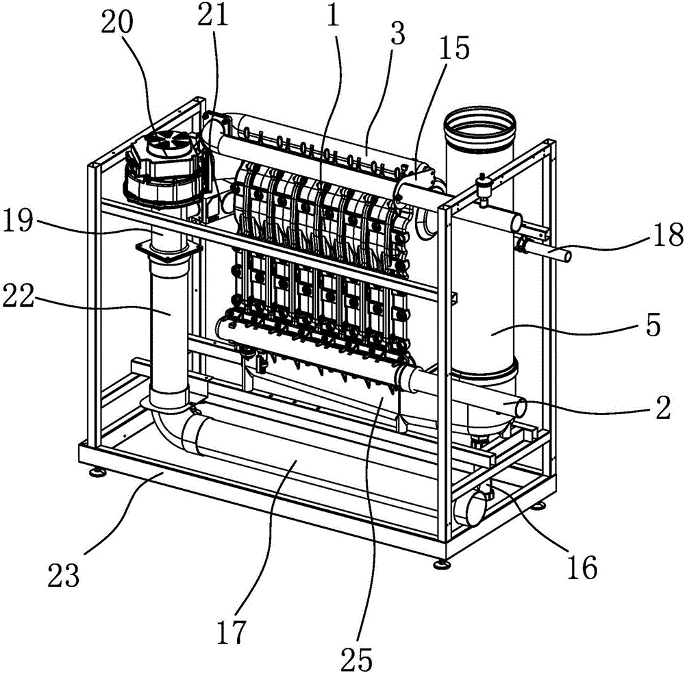
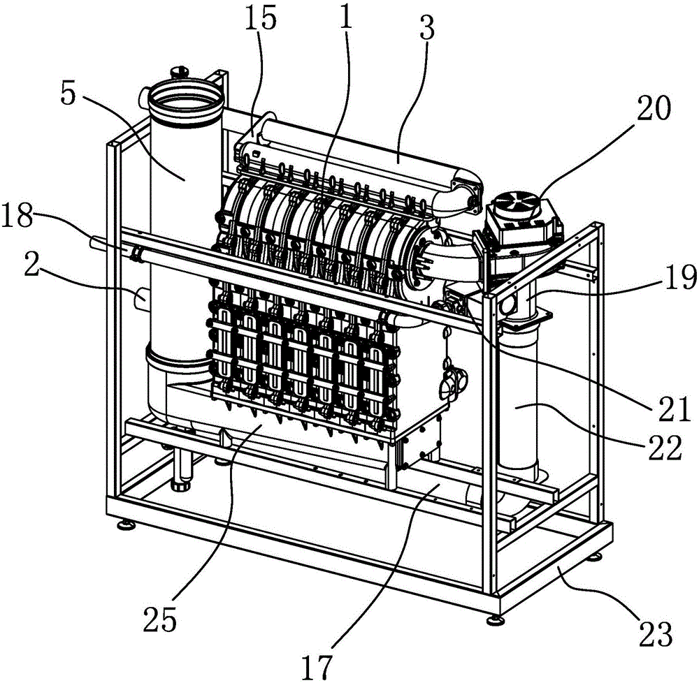
[0042] Such as figure 1 , figure 2 As shown, the condensing gas heating water heater includes a heat exchanger assembly 1, a water inlet pipe 2, an outlet pipe 3, a burner 4, a smoke exhaust pipe 5, an air inlet pipe 17, a gas inlet pipe 18, a gas mixer 19, Fan 20 and support 23.

[0043] Support 23 is a rectangular parallelepiped frame, and heat exchanger assembly 1, water inlet pipe 2, water outlet pipe 3, smoke exhaust pipe 5, air inlet pipe 17, gas inlet pipe 18 and blower fan 20 are all fixed on the bracket 23.

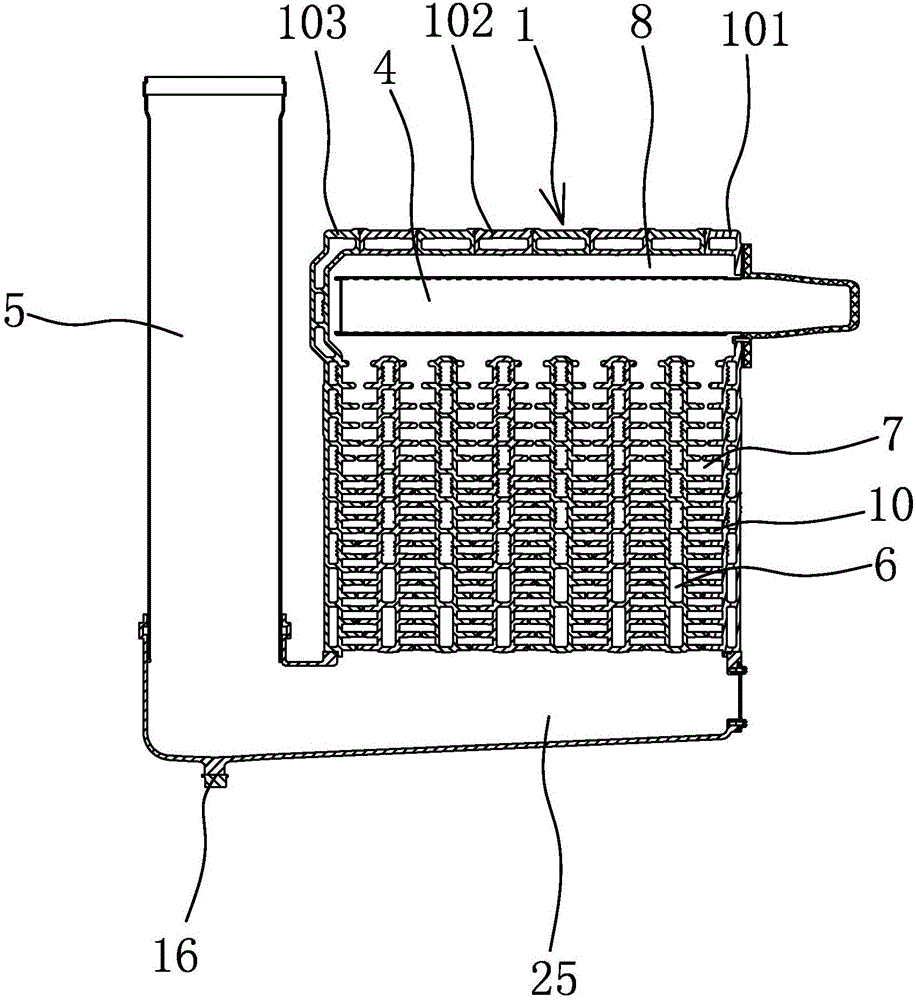
[0044] Such as Figure 4 , Figure 5 As shown, in the present embodiment, the heat exchanger assembly 1 includes a front sheet 101, a rear sheet 103 and six middle sheets 102. In actual production, the n...


PUM


Abstract

The invention provides a condensation type gas heating water heater and belongs to the technical field of water heaters. The condensation type gas heating water heater solves the problem that an existing water heater is low in heat exchange efficiency. The condensation type gas heating water heater comprises a heat exchanger assembly, a water inlet pipe, a water outlet pipe, a combustor and a smoke exhausting pipe; a plurality of water way channels and a plurality of flue gas channels are arranged in the heat exchanger assembly; the water way channels and the flue gas channels are arranged at intervals and are not communicated with one another; the water inlet pipe is located at the bottom of the heat exchanger assembly; the water outlet pipe is located on the top of the heat exchanger assembly; the water inlet pipe is communicated with the water outlet pipe through the water way channels; a combustion chamber is arranged in the top of the heat exchanger assembly; the flue gas channels are located below the combustion chamber; the combustor is located in the combustion chamber; the smoke exhausting pipe is communicated with the bottom of the heat exchanger assembly; and the smoke exhausting pipe is communicated with the combustion chamber through the flue gas channels. The condensation type gas heating water heater has the beneficial effect that the heat exchange efficiency is high.

Description

technical field [0001] The invention belongs to the technical field of water heaters, and relates to a condensing gas heating water heater. Background technique [0002] The gas water heater refers to the use of gas as a fuel to transfer heat to the cold water flowing through the heat exchanger through combustion and heating to achieve the purpose of preparing hot water. When ordinary gas-fired water heaters work, they will emit a large amount of flue gas. The temperature of the flue gas is as high as 180°C. During the process of high-temperature flue gas, the fuselage of the gas water heater will be obviously hot, which will reduce the service life of the gas water heater. [0003] For the above problems, people have made various improvements, and some have applied for patents. For example, Chinese patent documents disclose condensing gas heating water heaters [application number: 201220040228.X; authorized announcement number: CN202452687U], including a support box and a...

Claims


Application Information

Patent Timeline
IPC IPC(8): F24H1/22F24H9/00F24H9/16F24H9/18F24H9/20
CPCF24H1/22F24H9/0005F24H9/16F24H9/1836F24H9/2035
Inventor 姜宇光黄丹君李耀解恩军
Owner ZHEJIANG INOVISEN THERMAL ENERGY TECH CO LTD
Learn More