Method and apparatus for separation of fluids within a single vessel

a technology of fluid separation and single vessel, which is applied in the separation process, chemistry apparatus and process, and the nature of treatment water, etc., can solve the problems of increasing the cost and operating expense of having two machines, and not allowing the equipment to become portable, so as to achieve the effect of reducing the cost and operating expens

Active Publication Date: 2015-08-04
ENVIRO TECH SYST L L C
View PDF9 Cites 3 Cited by
  • Summary
  • Abstract
  • Description
  • Claims
  • Application Information

AI Technical Summary

Benefits of technology

[0009]Therefore, it is a principal object of the present invention wherein the combination of these two technologies in one vessel benefits the user in that it minimizes the cost and operating expense of having two machines for this operation.
[0010]It is a further object of the present invention whereby the combination provides a space savings over the current technology.
[0011]It is a further object of the present invention whereby the combination makes the equipment portable and therefore can be applied in several ways, primarily as process water treatment equipment, but also for using as equipment bypass treatment while existing equipment is being maintained and finally for pipeline flushes and cleaning and frac water treatment.
[0012]It is a further object of the present invention to provide a significant benefit to the state of the art when one considers that to this date all applications of these two techniques have been done in separate and individual equipments while taking up additional space, and having a significantly higher cost, considering the fact there is more equipment, maintenance and instrumentation.

Problems solved by technology

In the present state of the art, the separation of two distinct fluids is undertaken in separate operations, which requires additional space, increases the cost and operating expense of having two machines for this operation, and does not allow the equipment to become portable, since these technologies are being operated separately for all of the above applications.

Method used


Image

  • Method and apparatus for separation of fluids within a single vessel
  • Method and apparatus for separation of fluids within a single vessel
  • Method and apparatus for separation of fluids within a single vessel

Examples


Embodiment Construction

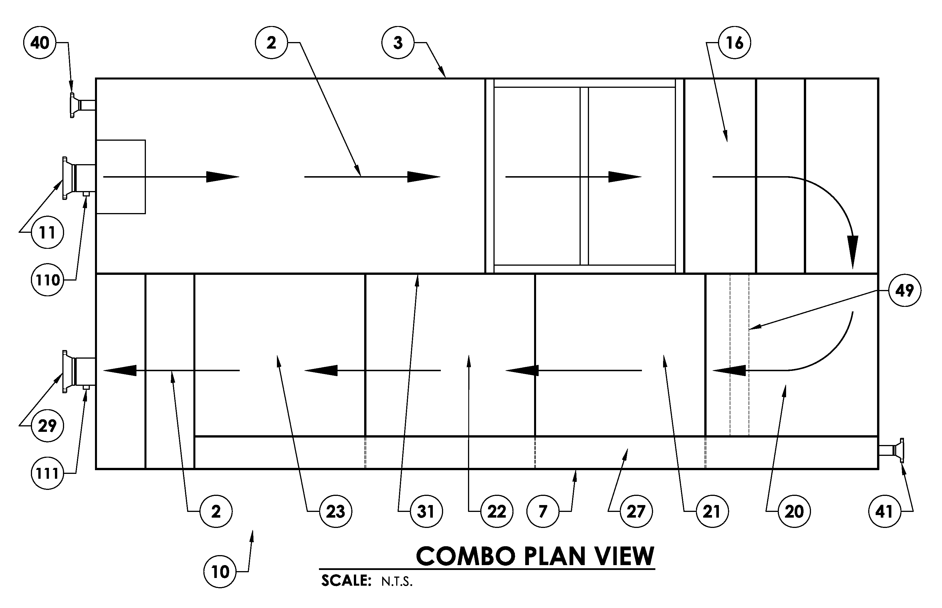
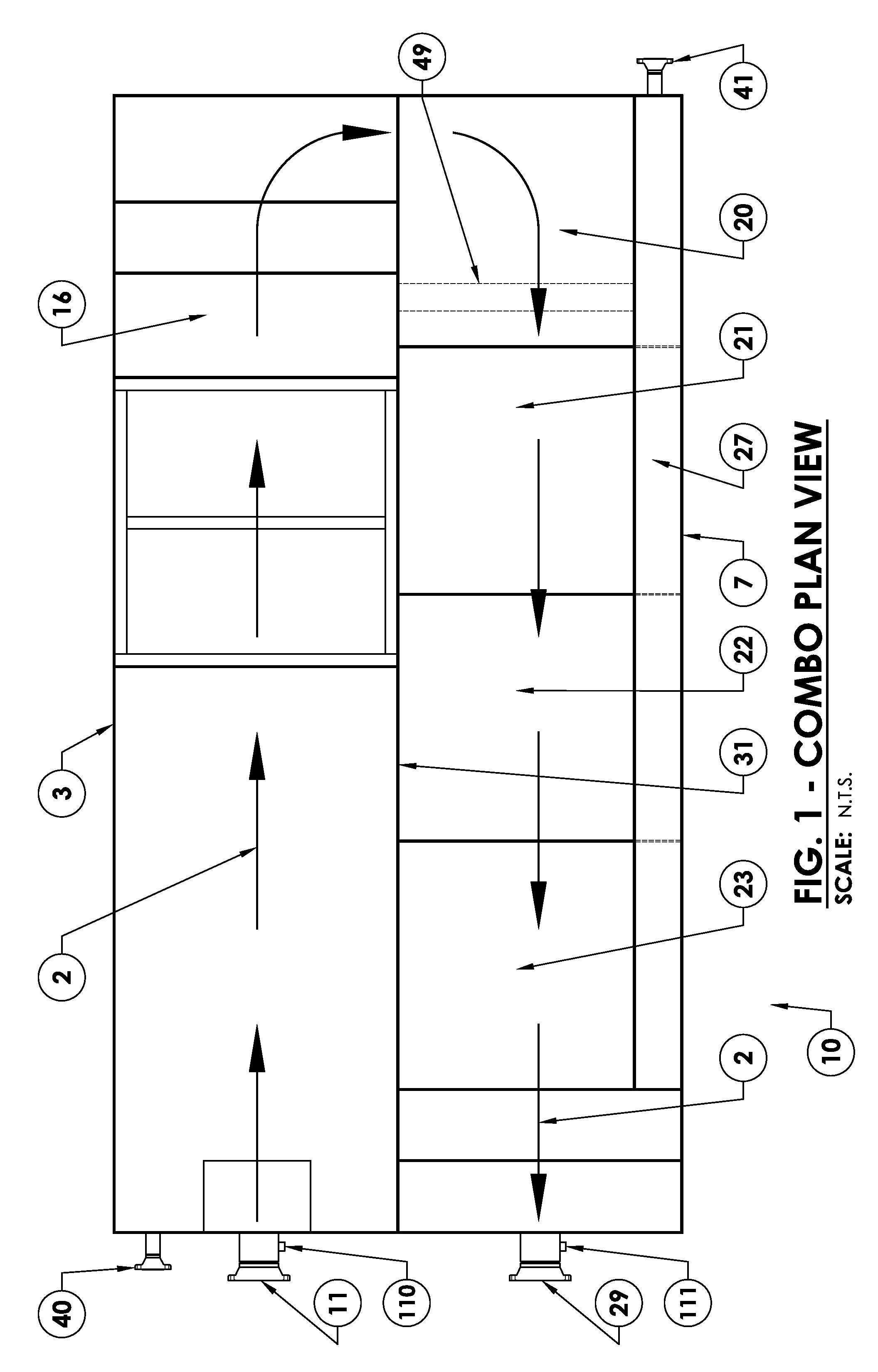
[0022]FIG. 1 illustrates a schematic plan view of the present invention, Enviro-Cell-Combo apparatus 10 of the present invention. Enviro-Cell apparatus 10 utilizes an immiscible fluids separation method, incorporating a Corrugated Plate Interceptor (CPI) compartmental vessel 3 conjoint with an Induced Gas Flotation (IGF) compartmental vessel 7 at CPI / IGF process separation partition 31. Schematically illustrated by the immiscible fluid primary flow path 2, the raw immiscible fluid to be separated enters the present invention at immiscible fluid inlet flange 11, the fluid proceeding subsequently through the separation method of Enviro-Cell-Combo 10, and finally a recovered portion of the process fluid (typically water) exiting the invention at clean water outlet flange 29. Oil separated during the initial phase of the immiscible fluids separation process is collected in oil collection reservoir (CPI) 16. In like manner, oil separated during the final phase of the immiscible fluids se...


PUM

PropertyMeasurementUnit
specific gravityaaaaaaaaaa
distanceaaaaaaaaaa
pressureaaaaaaaaaa

Abstract

A process wherein a combination of two separation principles are combined into one space saving machine with portability to separate two distinct and different fluids one lighter in specific gravity than the other, including the steps of primary separation of fluids allowing for free and suspended solids along with free oil and grease to be removed in the primary separation chamber; utilizing parallel corrugated plates in the separation defining the distance of rise for a given oil droplet based on Stokes Law to remove the remaining large droplets of free oil and solids; and providing an induced gas flotation process which provides a finely dispersed bubble in the liquid to accelerate the lift necessary for separation of fine oil droplets, emulsified oil droplet, and suspended solids to meet a government discharge regulation. This combined technique can be configured in a single vessel without pumps or other methods of liquid movement.

Description

CROSS-REFERENCE TO RELATED APPLICATIONS[0001]Priority of U.S. Provisional Patent Application Ser. No. 61 / 449,289, filed Mar. 4, 2011, incorporated herein by reference, is hereby claimed.STATEMENT REGARDING FEDERALLY SPONSORED RESEARCH OR DEVELOPMENT[0002]Not applicableREFERENCE TO A “MICROFICHE APPENDIX”[0003]Not applicableBACKGROUND OF THE INVENTION[0004]1. Field of the Invention[0005]The present invention relates to separation of fluids. More particularly, the present invention relates to a method for the separation of two liquids which are immiscible with each other. Still more particularly the present invention discloses a method and an apparatus for separating oil from water efficiently within a single vessel by applying a separating influence and minimizing other factors which tend to reduce droplet size and inhibit separation.[0006]2. General Background of the Invention[0007]In the present state of the art, the separation of two distinct fluids is undertaken in separate opera...

Claims


Application Information

Patent Timeline
Patent Type & Authority Patents(United States)
IPC IPC(8): C02F1/24B03D1/14B03D1/24B01D17/02C02F1/40C02F103/36
CPCC02F1/40B01D17/0205C02F1/24B01D17/0214B03D1/1406B01D17/0211B03D1/1456B03D1/1493C02F2103/365B03D1/1475B03D1/1487B03D1/24
Inventor RICHERAND, FRANK A.
Owner ENVIRO TECH SYST L L C
Why Eureka
Try Eureka