Device forming a manometer intended for measuring biphasic fluid pressure, associated method of manufacture and fluidic network

a manometer and biphasic technology, applied in the field of manometers, can solve the problems of not being able to be integrated in a fluidic network, macroscopic measurement devices thus proposed,

Inactive Publication Date: 2015-08-04
COMMISSARIAT A LENERGIE ATOMIQUE ET AUX ENERGIES ALTERNATIVES
View PDF13 Cites 3 Cited by
  • Summary
  • Abstract
  • Description
  • Claims
  • Application Information

AI Technical Summary

Benefits of technology

[0055]Thus, on the basis of this analysis, the inventors reached the conclusion that by varying the wetting angle (contact angle), it was possible to increase very substantially the measuring sensitivity of a manometer the measuring principle of which is the position of a liquid meniscus.
[0056]In other words, the inventors concluded that through the use of a surface energy gradient the measuring sensitivity of a manometer is able to be increased, compared to a hydrophobic surface with constant surface energy. In addition, they concluded that this increased measuring sensitivity is still more important with a 2nd order angle cosine gradient, compared to a linear cosine gradient.
[0057]Thus, due to its great measuring sensitivity, a device according to the invention can be of microscopic dimensions for relatively small pressure variations, typically of the order of 1 bar. It may therefore be incorporated in a fluidic network without impairing its compactness or its operation.
[0084]Control of the etching / ablation design thus enables a surface chemical gradient to be produced. The gradient can also be obtained by evaporation of a functionalised molecule.

Problems solved by technology

The dimensions of the measuring device thus proposed are macroscopic, and do not allow it to be integrated in a fluidic network of a compact system.

Method used


Image

  • Device forming a manometer intended for measuring biphasic fluid pressure, associated method of manufacture and fluidic network
  • Device forming a manometer intended for measuring biphasic fluid pressure, associated method of manufacture and fluidic network
  • Device forming a manometer intended for measuring biphasic fluid pressure, associated method of manufacture and fluidic network

Examples


Embodiment Construction

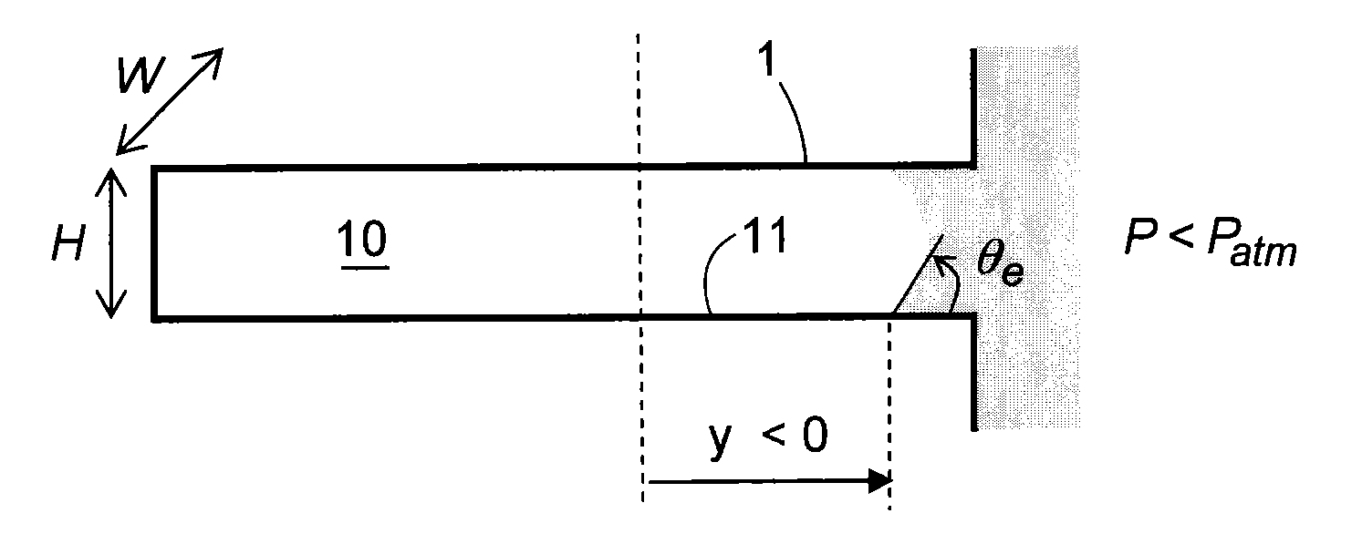
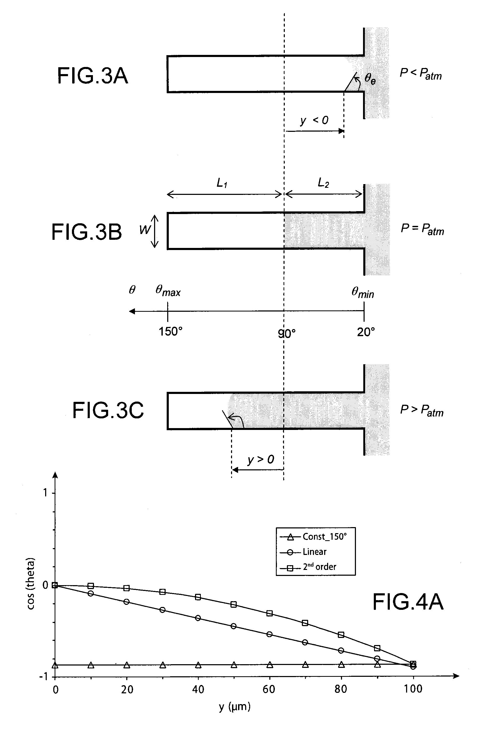
[0012]To accomplish this, the object of the invention is a device forming a manometer, intended to measure the pressure of a biphasic fluid in a fluidic network, including:[0013]a first channel inside which a biphasic fluid is able to flow,[0014]a second channel emerging into the first channel, where the second channel is blind, with each of its dimensions less than the capillary length of the fluid's liquid phase, and with its lengthways wall having a surface energy gradient which decreases from its inlet to the end, where the surface energy gradient enables the wetting angle of the meniscus of the fluid's liquid phase to be increased in the blind channel from its inlet to the end.

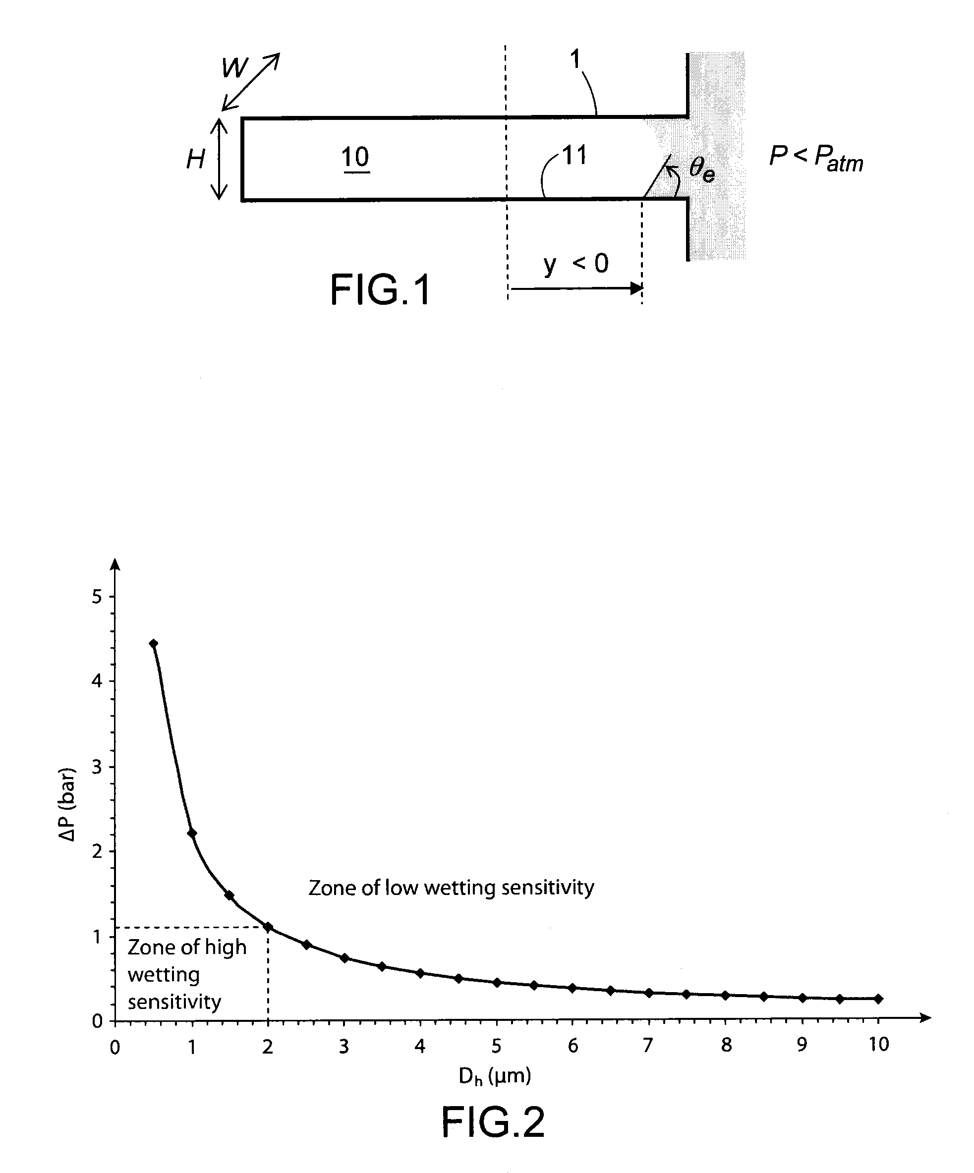
[0015]Capillary length is a characteristic dimension of a liquid in relation at which the capillary forces and gravitational forces are of the same magnitudes. In the case of water, the capillary length lc and the capillary volume Vc have the following respective values:

[0016]lc⁢∼σρ.g∼2.7⁢⁢mmandvc⁢∼43.π.(...


PUM

PropertyMeasurementUnit
lengthaaaaaaaaaa
lengthaaaaaaaaaa
displacementaaaaaaaaaa

Abstract

A device forming a manometer, configured to measure pressure of a biphasic fluid in a fluidic network, including: a first channel inside which a biphasic fluid is able to flow; a second channel emerging into the first channel, wherein the second channel is blind, with each of its dimensions less than capillary length of the fluid's liquid phase, and with at least one of its lengthways wall having a surface energy gradient that decreases from its inlet to the end. The surface energy gradient enables the wetting angle of the meniscus of the fluid's liquid phase to be increased in the blind channel from its inlet to the end. Such a device may find application to measurement of pressure of a biphasic fluid in a heat exchanger or in a fuel cell.

Description

TECHNICAL FIELD[0001]The invention concerns a device forming a manometer, intended to measure the pressure of a biphasic fluid in a fluidic network.[0002]It relates to an improvement of the sensitivity of a manometer, allowing a manifest reduction of the dimensions and its incorporation in a fluidic network.[0003]The applications at which the invention is directed in particular are biphasic fluid heat exchangers, fuel cells or other systems involving the use of a biphasic blend operating at around atmospheric pressure.PRIOR ART[0004]In systems such as a biphasic fluid heat exchanger or a fuel cell, the liquid and vapour phases of a given fluid are simultaneously present in the fluidic network supporting the heat and mass exchanges.[0005]The pressure of the fluid, the mass flow ratio between the vapour and liquid phases (titre) of the biphasic fluid, together with their respective distributions in the fluidic network, are parameters which reveal, at all times, the system's operationa...

Claims


Application Information

Patent Timeline
Patent Type & Authority Patents(United States)
IPC IPC(8): G01L7/18G01L9/00
CPCG01L7/18G01L9/0095Y10T137/8326Y10T29/494Y10T29/49224
Inventor PHAN, HAI TRIEUCORONEL, PHILIPPEFUGIER, PASCALGAVILLET, JEROME
Owner COMMISSARIAT A LENERGIE ATOMIQUE ET AUX ENERGIES ALTERNATIVES
Why Eureka
Try Eureka