High reflective board or substrate for LEDs

a technology of leds and substrates, applied in semiconductor/solid-state device manufacturing, semiconductor devices, electrical devices, etc., can solve the problems of increasing the amount of light that can be emitted by led devices, and achieve the effects of improving the reflectivity of substrates, boards or sub-mounts, and reducing the absorption of led ligh

Active Publication Date: 2015-08-11
CREELED INC
View PDF165 Cites 7 Cited by
  • Summary
  • Abstract
  • Description
  • Claims
  • Application Information

AI Technical Summary

Benefits of technology

[0016]The present invention provides light emitting devices and methods directed to improved light output. The different embodiments according to the present invention are arranged to provide improved reflectivity of the substrates, boards or submounts, thereby reducing the absorption of LED light. This in turn increases the amount of light that can emit from the LED device. The LED devices also exhibit improved emission characteristics of the device over its lifetime by having a reflective coating on the submount that is substantially non-yellowing.

Problems solved by technology

This in turn increases the amount of light that can emit from the LED device.

Method used


Image

  • High reflective board or substrate for LEDs
  • High reflective board or substrate for LEDs
  • High reflective board or substrate for LEDs

Examples


Embodiment Construction

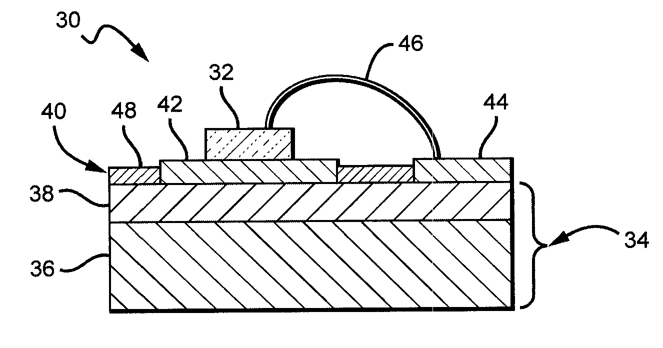
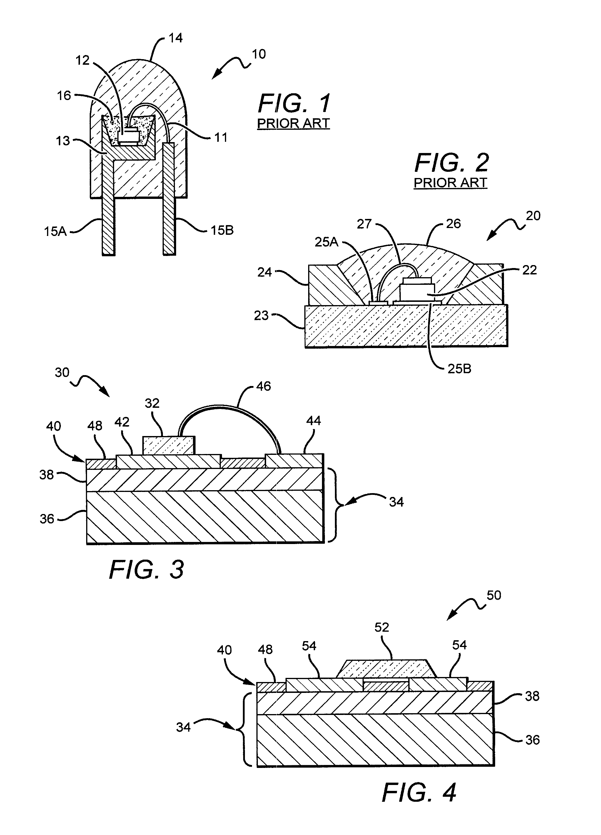
[0041]The present invention provides structures and methods for producing light emitting devices, such as single or multi-chip LED devices, packages, arrays and lamps that provide high luminous flux output. The electronic elements may include one or more circuit boards with one or more light emitting diodes (LEDs), solar cells, photodiodes, laser diodes, and other such optoelectronic elements or combinations of optoelectronic elements. Several possible embodiments of the present invention are generally directed to light emitting devices incorporating LEDs, but it is understood that other light emitting devices may also be used.

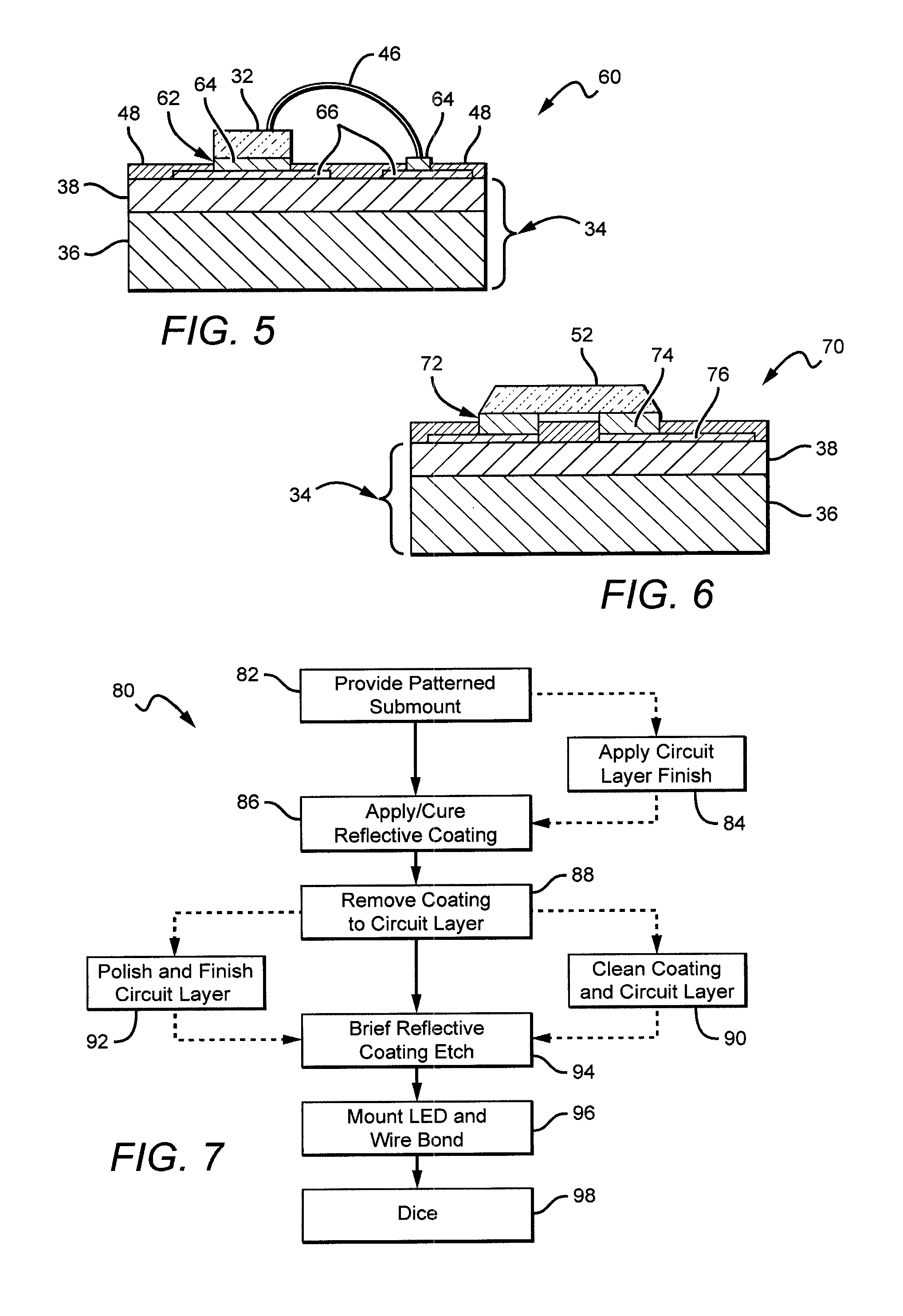
[0042]The present invention generally provides devices and methods for manufacturing light emitting devices for increasing light output using a high reflective coating on the board, substrate or submount. The reflective coating can effectively redirect light that is back-emitted from the emitter, back-scattered or reflected by a light diffusion lens, light sca...


PUM


Abstract

Light emitting devices and methods are disclosed that provide improved light output. The devices have an LED mounted to a substrate, board or submount characterized by improved reflectivity, which reduces the absorption of LED light. This increases the amount of light that can emit from the LED device. The LED devices also exhibit improved emission characteristics by having a reflective coating on the submount that is substantially non-yellowing. One embodiment of a light emitting device according to the present invention comprises a submount having a circuit layer. A reflective coating is included between at least some of the elements of the circuit layer. A light emitting diode mounted to the circuit layer, the reflective coating being reflective to the light emitted by the light emitting diode. In some embodiments, the reflective coating comprises a carrier with scattering particles having a different index of refraction than said carrier material.

Description

[0001]This application is a continuation-in-part from, and claims the benefit of U.S. patent application Ser. No. 13 / 017,778, to Andrews, filed on Jan. 31, 2011, and entitled “Solid State Lighting Component Package With Reflective Layer, and U.S. patent application Ser. No. 12 / 757,179 to Yuan et al., filed Apr. 9, 2010 and entitled “High Reflective Substrate of Light Emitting Devices With Improved Light Output.”BACKGROUND OF THE INVENTION[0002]1. Field of the Invention[0003]The present invention relates generally to light emitting devices, packages or lamps, and more particularly to these devices having highly reflective properties for improved light output.[0004]2. Description of the Related Art[0005]Light emitting diodes (LED or LEDs) are solid state devices that convert electric energy to light and generally comprise an active region of semiconductor material sandwiched between two oppositely doped layers of semiconductor material. When a bias is applied across the doped layers, ...

Claims


Application Information

Patent Timeline
Patent Type & Authority Patents(United States)
IPC IPC(8): H01L33/46H01L33/60H01L33/54H01L33/62
CPCH01L33/60H01L33/54H01L33/62H01L2224/48091H01L2924/00014H01L2224/73265
Inventor HEIKMAN, STENYAO, ZHIMIN JAMIEIBBETSON, JAMESZHANG, FAN
Owner CREELED INC
Why Eureka
Try Eureka