Detachable shaft flexible endoscope

a flexible endoscope and flexible technology, applied in the field of endoscopes, can solve the problems of increasing the complexity of the endoscope, increasing the risk of damage, and affecting the operation of the endoscope, so as to achieve the effect of convenient attachmen

Active Publication Date: 2015-08-18
KARL STORZ ENDOVISION INC
View PDF38 Cites 195 Cited by
  • Summary
  • Abstract
  • Description
  • Claims
  • Application Information

AI Technical Summary

Benefits of technology

[0010]Accordingly, it is an object of the present invention to provide an endoscopic instrument having a handle and a flexible shaft, wherein the flexible shaft can easily be attached and detached from the handle. Related to this object, the endoscope should be configured such that the internal components that are fragile and delicate are concentrated in one section of the instrument.
[0012]It is yet another object of the present invention to provide a flexible endoscope having a handle and a detachable flexible shaft, wherein the handle and the shaft are each adapted to prevent and / or reduce the likelihood of contamination (from fluids, germs, bacteria) of their internal components when in a detached configuration. It is also an object to provide an endoscope, wherein, when the handle and flexible shaft are coupled to each other, they collectively prevent and / or reduce the likelihood of contamination of their internal components and the interface between each section of the endoscope.
[0021]The articulation unit may comprise at least one tension wire that is coupled to the distal end of the flexible shaft and extends to the steering control. In some embodiments, a plurality of tension wires may be used in the articulation unit, providing increased precision and accuracy in the deflection of the distal portion of the flexible shaft. By movement or manipulation of the steering control, a tension (e.g., pushing, pulling) is applied directly to the at least one tension wire, which subsequently produces a bending motion in the distal portion of the shaft. In other embodiments, the articulation unit may comprise an actuator disposed in the shaft and connected between the steering control and the at least one tension wire. When the steering control is moved or manipulated, a steering signal representing a tensile force and a direction of deflection is sent to the actuator. The actuator then applies a tension to the tension wire based on the signal. The amount and direction in which the distal portion of the shaft bends is correlated to the applied tensile force. With either configuration, the articulation unit is capable of precisely deflecting the flexible shaft in small increments.
[0024]With delicate components of the instrument being located within one section, i.e., the flexible shaft, and the handle having the robust drive electronics (e.g., imaging control unit, illumination control), this arrangement provides for easier means of locating and diagnosing problems / issues with the endoscope, repairing the instrument, and / or replacing parts of the instrument. More specifically, if the flexible endoscope has a problem with deflecting or providing sufficient illumination, it may be determined quickly that the issue resides in the shaft. The user can then easily detach the malfunctioning shaft, send it to the manufacturer for repair, and substitute / replace the malfunctioning shaft with a new one, without substantial downtime.
[0025]Additional objects of the invention are achieved by providing an endoscope including a handle, a flexible shaft, and a coupling mechanism for attaching the flexible shaft to the handle, the coupling mechanism having a first component disposed on the proximal end of the flexible shaft and a second component disposed on a distal end of the handle, wherein the first and second components are adapted to engage each other. The first and second components also independently seal the shaft and handle, respectively, from fluid leakage and contamination with germs, bacteria, or other biological materials. In particular, the first and second components are adapted to provide fluid-proof, static seals that prevent or reduce the likelihood of communication of fluid into the interior compartments of the flexible shaft and handle. The seals enable both parts of the endoscope to be reprocessed (i.e., cleaned, disinfected and sterilized) while in a detached configuration. Further, upon coupling the shaft to the handle, the first and second components collectively create a seal therebetween to prevent any contamination of the interior compartments as well as the coupling mechanism itself.

Problems solved by technology

Since then, the endoscope has grown increasingly complex, incorporating a flexible shaft, a shaft with a working channel for communicating fluids or medical tools, mechanical components extending from the handle to articulate the shaft, a light source embedded within the handle, optical fiber bundles for transmitting an image from a distal end of the shaft to an eyepiece on the handle, and / or distal imagers.
However, as the endoscope becomes more complex, component failure and failure due to damage also increases, especially with regard to fragile components positioned within the shaft section of the endoscope.
This is particularly true for flexible endoscopes, wherein delicate components within the flexible shaft, including the outer sheath, may be subjected to excessive bending, twisting, coiling, and fluid contamination.
When one of these internal components is damaged or fails, the entire endoscopic device requires extensive repair.
This requires a significant amount of down time (e.g., repair time, shipping time to and from the manufacturer) in which the medical practitioner / surgeon is without the endoscope.
However, this option still involves some downtime and requires that the surgeon pay extra fees for renting the loaner-endoscope in addition to paying the costs of repairing the damaged endoscope.
The endoscope does not allow the shaft to be separated from the handle and instead provides for the imaging unit to be detachable.
This design of the endoscope has significant drawbacks.
The shaft is rigid and is not as maneuverable in tight areas of a body cavity as a flexible, articulating shaft.
If there was a problem with the endoscope capturing an image, it may not be readily apparent to the surgeon whether the rod lens system in the shaft and / or the imaging unit was causing the problem.
If the light guide is damaged, then the entire endoscope—shaft and handle—has to be sent for repair.
The optical image fiber, therefore, is exposed and susceptible to damage during the process of attaching / detaching the shaft to the handle.
However, dynamic seals have a finite lifetime and are prone to wear and leakage.
Both shaft and handle lack the capability to detect any leaks and discharge any fluids that enter into their interiors.
If a distorted image was displayed at the eyepiece, the problem could be caused by damage to either the optical image fiber or the optics module.
As a result, both the shaft and the handle would still have to be sent to the manufacturer for proper diagnosis and repair.
Like the above prior art, it would not be readily apparent which optical component is the cause of the problem and therefore both the handle and the shaft must be sent for diagnosis and repair.
The shaft, therefore, fails to be completely sealed and cannot prevent leakage of fluid into the interior of the shaft.
In addition, the shaft fails to include a device for detecting and removing fluid therein.
This design has significant drawbacks.
The extreme section, which contains delicate components of the endoscope, is exposed and susceptible to damage during attachment / detachment of the shaft into the handle.
Because of the drawbacks of dynamic seals, the interiors—and internal components—of the handle and shaft are susceptible to damage and / or contamination by fluid leaking therein.
None of the above prior art references discloses a detachable shaft flexible endoscope having a design which is not prone to damage during attachment and detachment of the shaft to and from the handle.
Further, the endoscopes fail to provide sufficient sealed enclosures for the shaft and handle when detached from each other and lack any means for detecting fluid leakage.
Accordingly, delicate components are located within both sections of the endoscope, thereby requiring that the handle and shaft be sent for repair when a malfunction occurs.

Method used


Image

  • Detachable shaft flexible endoscope
  • Detachable shaft flexible endoscope
  • Detachable shaft flexible endoscope

Examples


Embodiment Construction

[0037]The following detailed description illustrates the invention by way of example, not by way of limitation of the principles of the invention. This description will enable one skilled in the art to make and use the invention, and describes several embodiments, adaptations, variations, alternatives and uses of the invention, including what is presently believed to be the best mode of carrying out the invention.

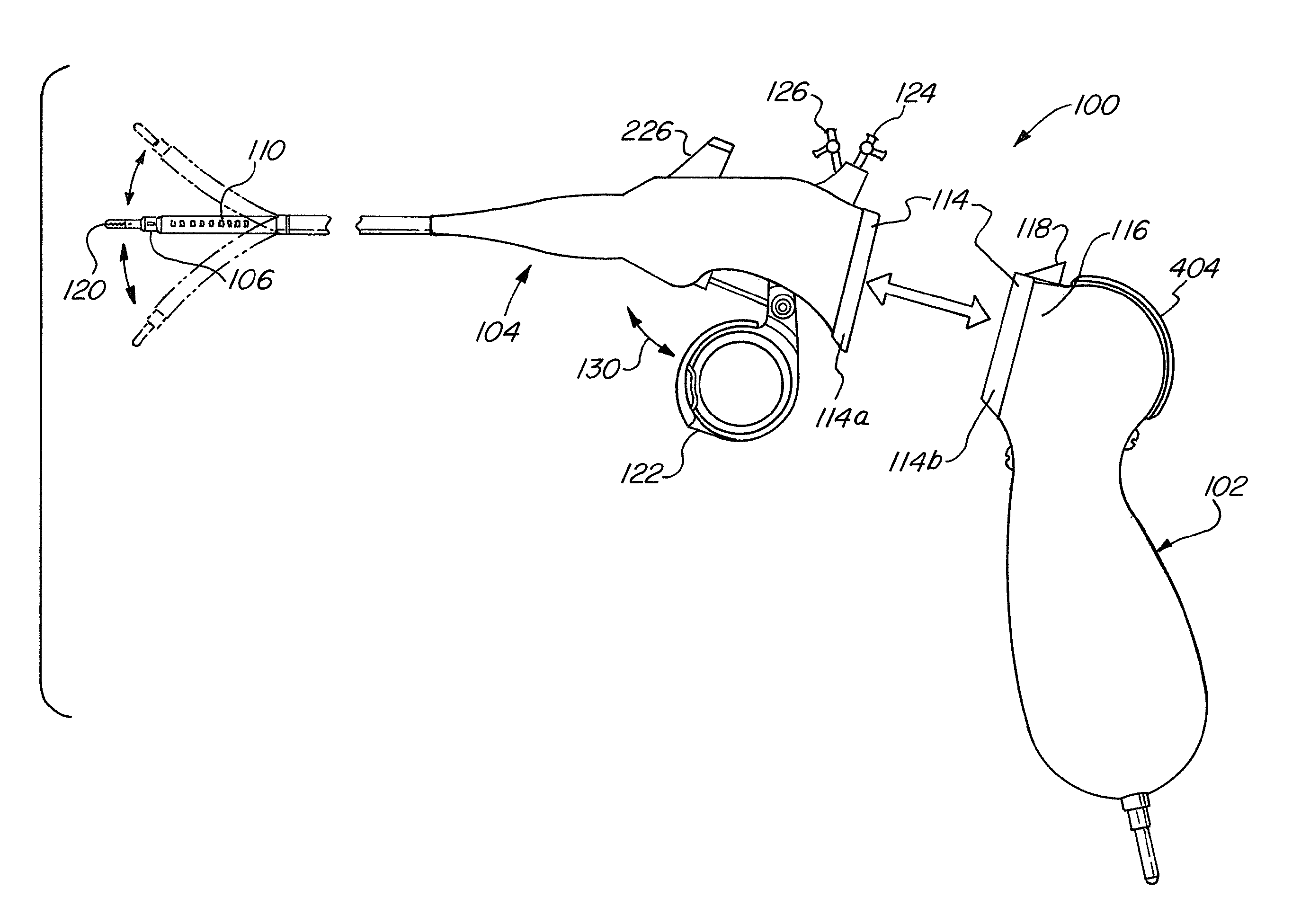
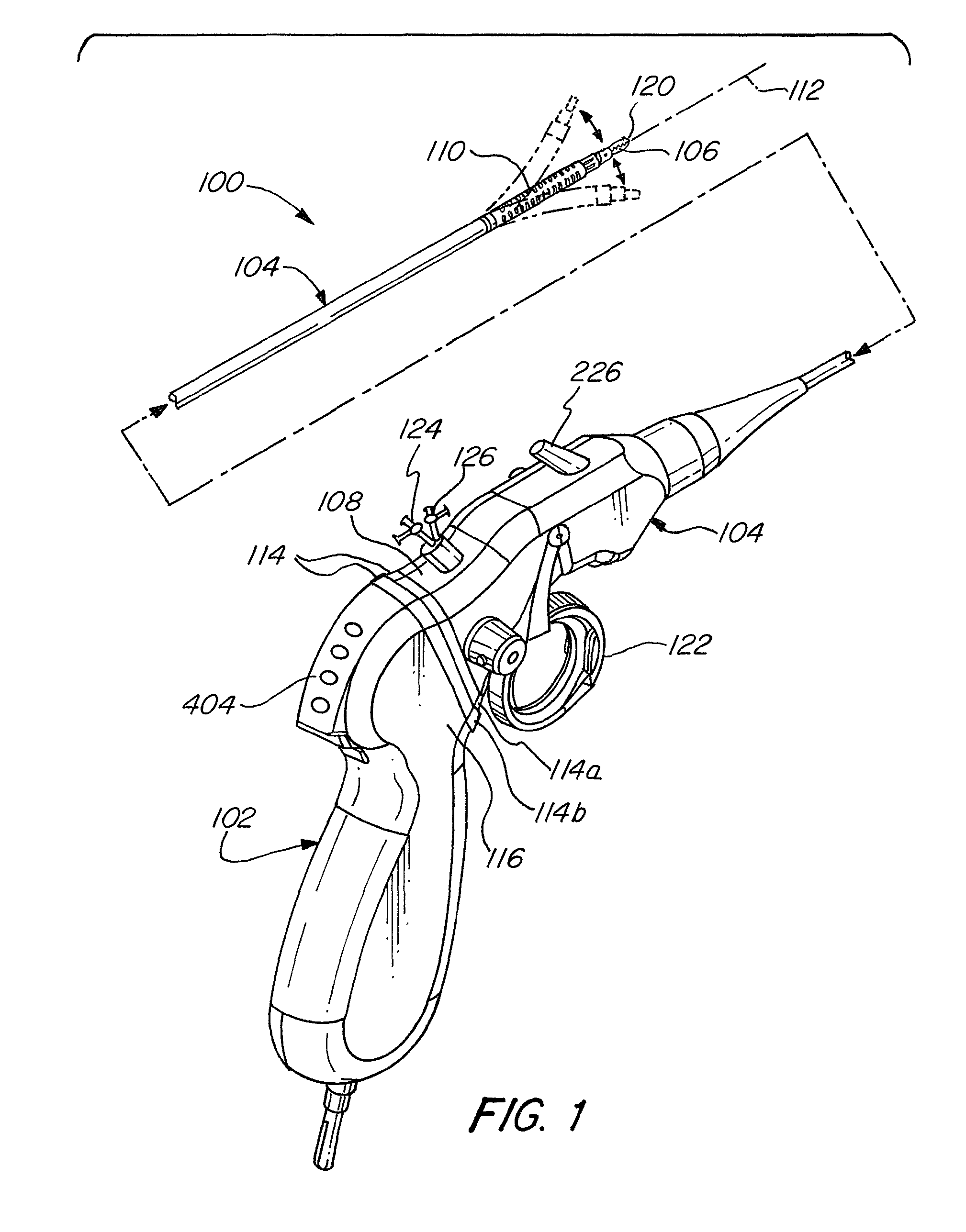
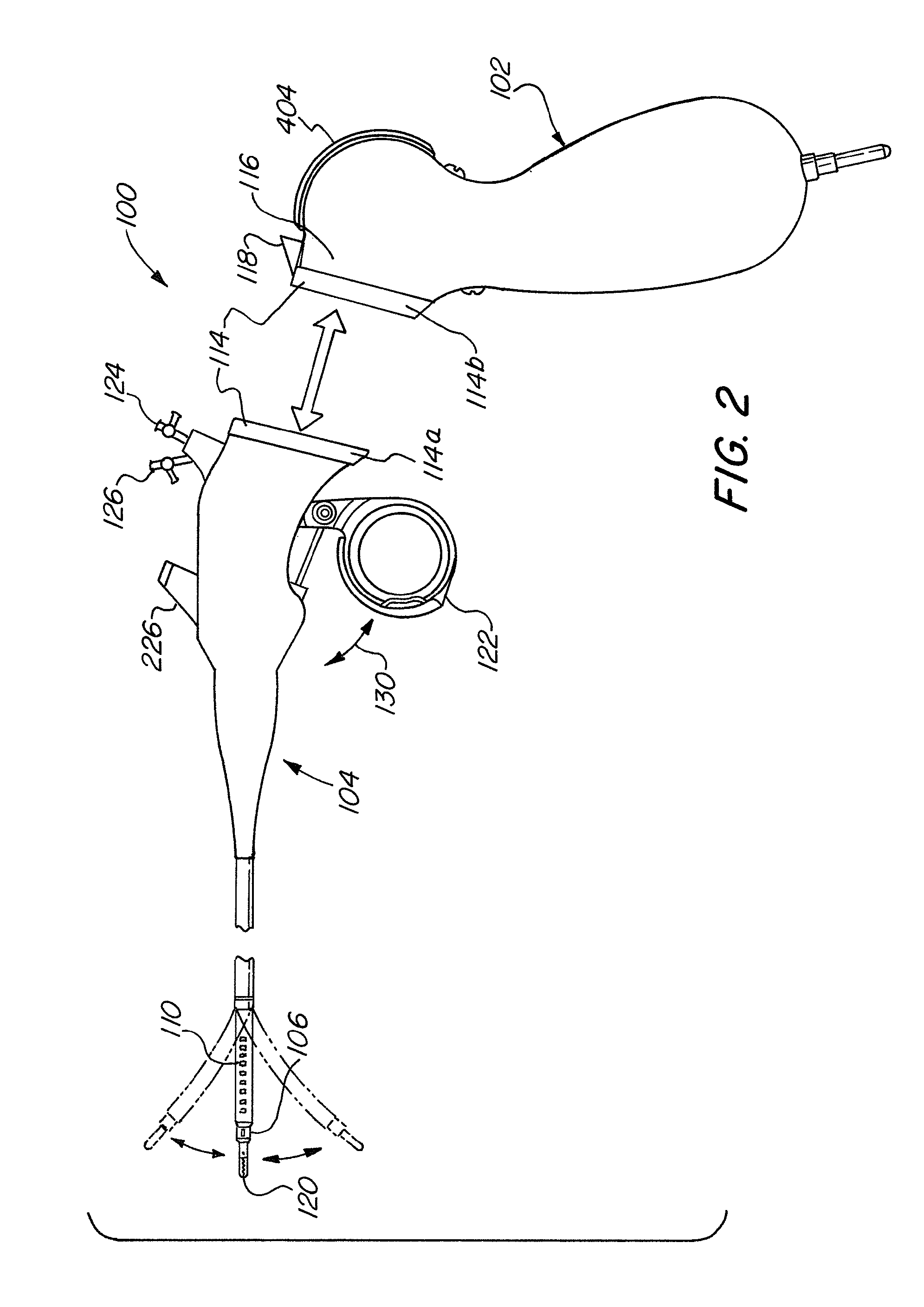
[0038]Referring to the figures in detail and first to FIGS. 1-2, there is shown a flexible endoscope 100 according to an exemplary embodiment of the present invention. The flexible endoscope 100 includes a handle 102 and a flexible shaft 104. The flexible shaft 104 has a distal end 106 and a proximal end 108, wherein the flexible shaft 104 is adapted to be inserted into a cavity of a living body (“operative site”). A distal portion (or bending portion) 110 disposed proximally from the distal end 106 can be articulated and deflected in any direction within a plane relative t...


PUM


Abstract

A flexible endoscope includes a handle, a flexible shaft having a distal end and a proximal end, a coupling mechanism releasably attaching the handle to the distal end of the flexible shaft, an illumination unit disposed in the flexible shaft, the illumination unit providing light to an area in front of the distal end of the flexible shaft, and an imaging unit disposed in the flexible shaft, the imaging unit generating image data of the area in front of the distal end of the flexible shaft, wherein the coupling mechanism includes an electrical channel for transmitting electrical power to the illumination unit and the imaging unit, and a data channel for transmitting the image data from the imaging unit.

Description

FIELD OF THE INVENTION[0001]This invention relates to an endoscope, and more specifically to a detachable shaft flexible endoscope having a coupling mechanism which releasably attaches a flexible shaft to a handle and provides operable connections for internal components of the flexible shaft to the handle.BACKGROUND OF THE INVENTION[0002]Endoscope technology has advanced significantly since its initial creation. Early endoscopic devices included a rigid, substantially linear shaft permanently attached to a handle, a light delivery system extending from the shaft to the handle and receiving light from an external source, and a plurality of optical lens for transmitting an image to an eyepiece. Since then, the endoscope has grown increasingly complex, incorporating a flexible shaft, a shaft with a working channel for communicating fluids or medical tools, mechanical components extending from the handle to articulate the shaft, a light source embedded within the handle, optical fiber ...

Claims


Application Information

Patent Timeline
Patent Type & Authority Patents(United States)
IPC IPC(8): A61B1/04A61B1/005A61B1/00
CPCA61B1/00114A61B1/005A61B1/00016A61B1/00066A61B1/00105A61B1/00124A61B1/00032A61B1/00057
Inventor BIRNKRANT, DASHIELL A.
Owner KARL STORZ ENDOVISION INC
Why Eureka
Try Eureka