
Compressor airfoil tip clearance optimization system

a compressor and airfoil technology, applied in the field of turbine engines, can solve the problems of compressor airfoils striking the compressor casing or the rotatable, the compressor cannot be simply placed in the components, and the gap is minimal, so as to enhance the effectiveness of axial movement, reduce the tip clearance, and minimize the compressor blade tip clearance

Inactive Publication Date: 2015-08-18
SIEMENS ENERGY INC
View PDF14 Cites 6 Cited by
  • Summary
  • Abstract
  • Description
  • Claims
  • Application Information

AI Technical Summary

Benefits of technology

The system reduces gas leakage and prevents damage by optimizing tip clearances during operation, increasing the efficiency of the turbine engine while ensuring necessary clearance for warm startup conditions.

Problems solved by technology

However, reducing the gap cannot be accomplished by simply positioning the components so that the gap is minimal under full load conditions because the configuration of the components forming the gap must account for warm restart conditions in which the compressor casing and the compressor vane carriers, having less mass than the compressor blade and disc assembly, cools faster than the compressor blade and disc assembly.
Therefore, unless the components have been positioned so that a sufficient gap has been established between the compressor blades and the compressor casing and between the compressor vanes and the rotatable compressor blade and disc assembly under operating conditions, the compressor airfoils may strike the compressor casing or the rotatable compressor blade and disc assembly because the diameter of components forming the compressor casing have not heated up and expanded yet.
Collision between the compressor blades and the compressor casing or compressor vanes and the rotatable compressor blade and disc assembly often causes severe airfoil tip rubs and may result in damage.

Method used


Image

  • Compressor airfoil tip clearance optimization system
  • Compressor airfoil tip clearance optimization system
  • Compressor airfoil tip clearance optimization system

Examples


Embodiment Construction

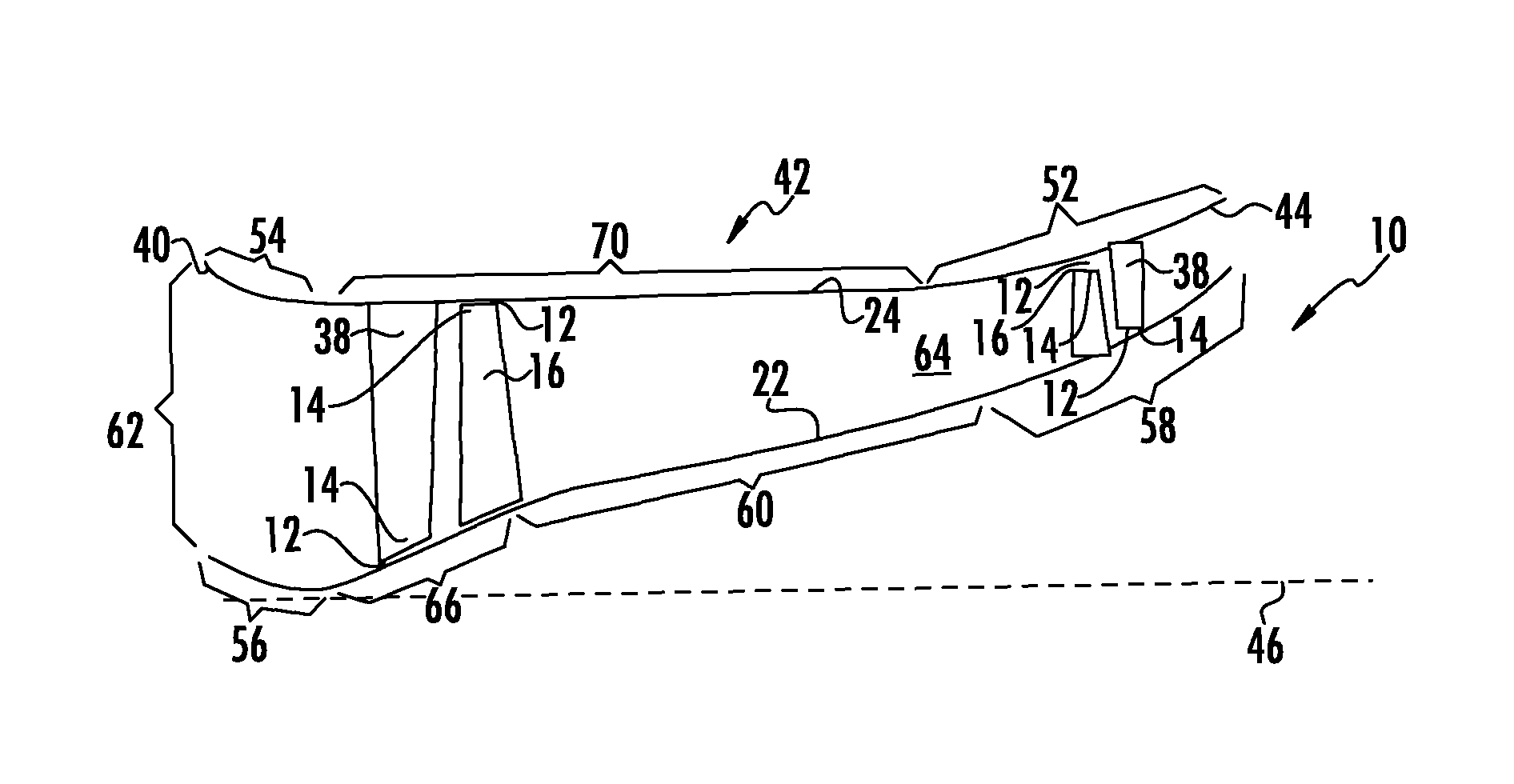
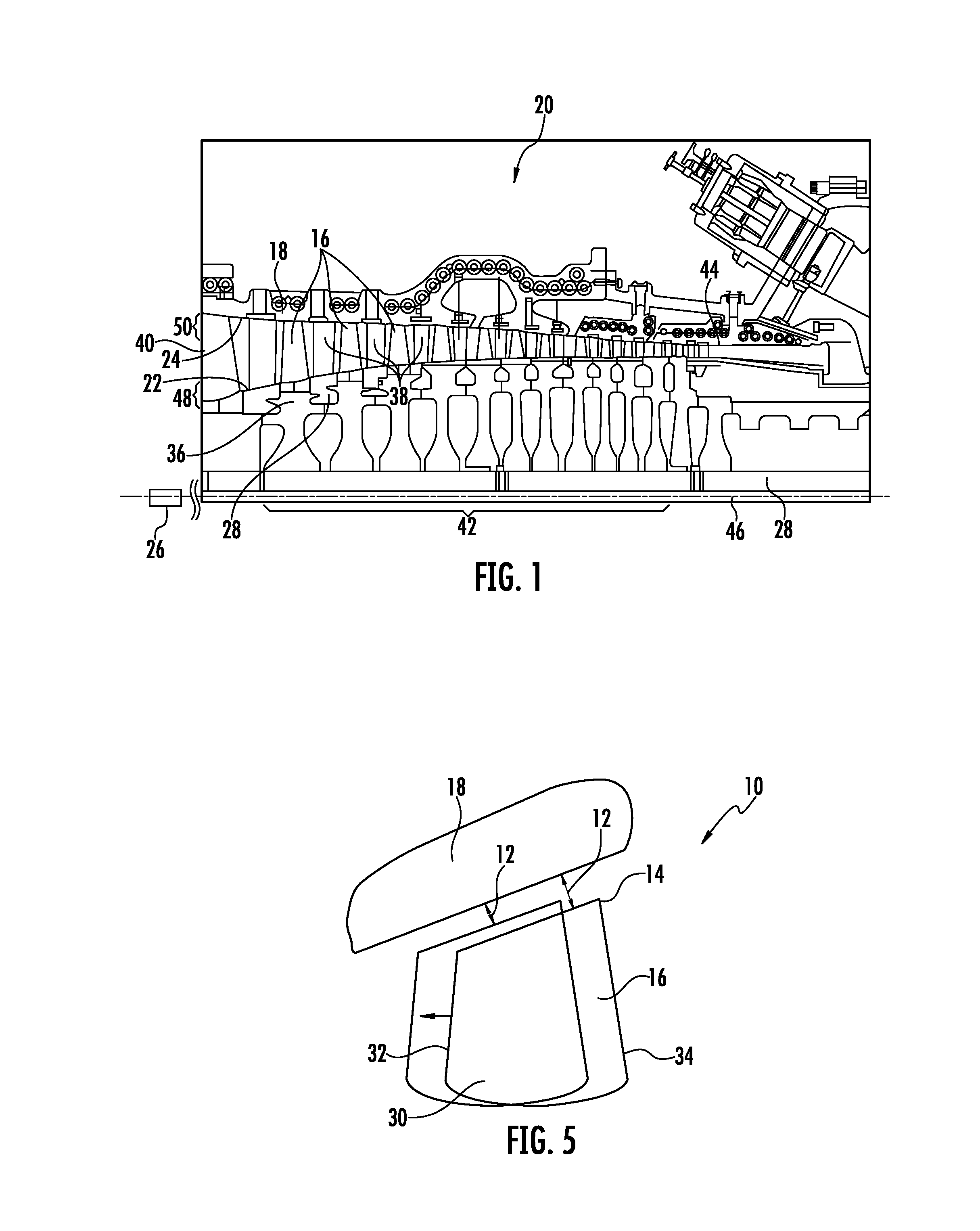
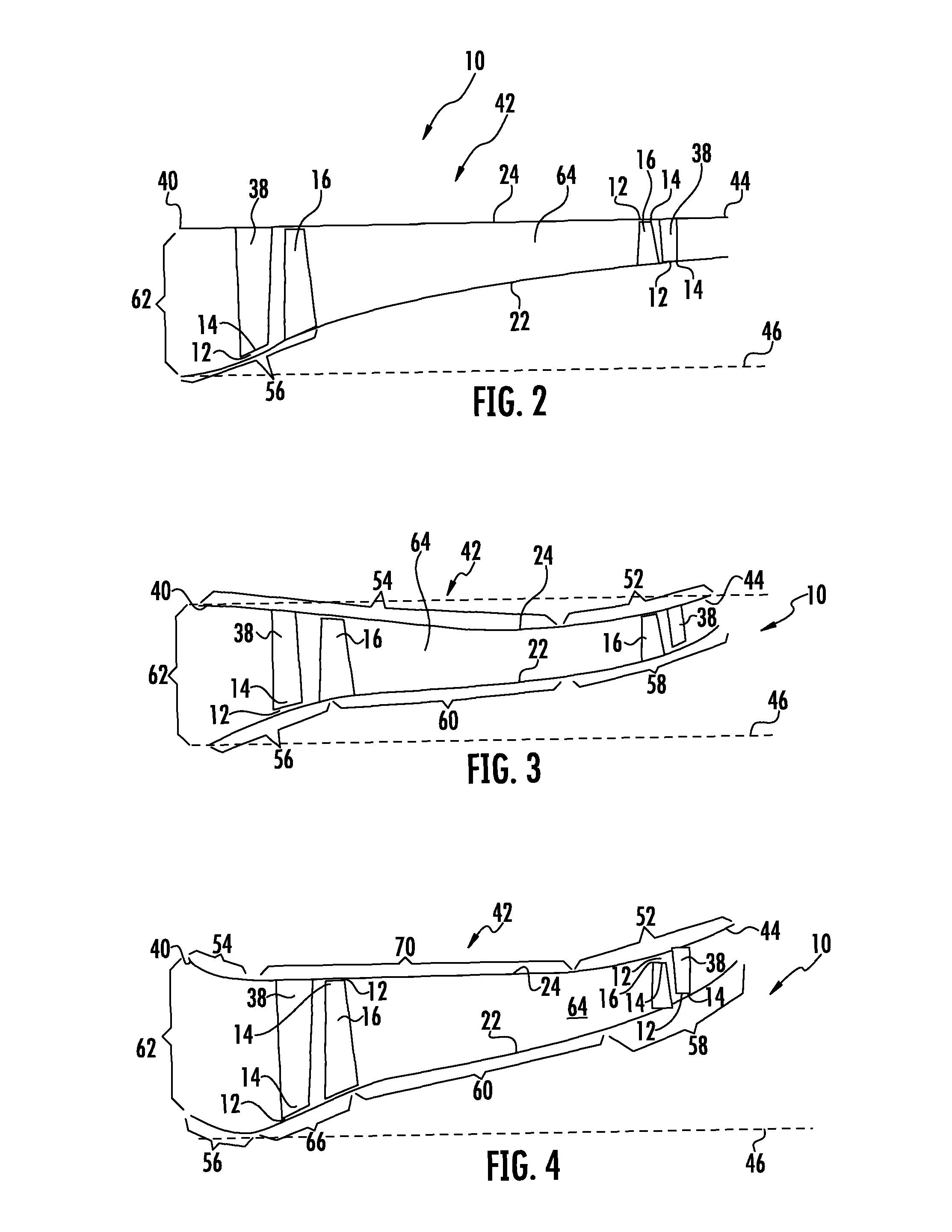
[0020]As shown in FIGS. 1-5, this invention is directed to a compressor airfoil tip clearance optimization system 10 for reducing gaps 12 between, tips 14 of compressor airfoils, such as compressor blades 16 and compressor vanes 38, and a compressor casing 18 of a turbine engine 20. The gaps 12 exists in the turbine engine 20 so that the tips 14 do not contact radially adjacent components, such as, the compressor casing 18 and the radially inward ID flowpath boundary 22 formed by the compressor rotor assembly 28, while the turbine engine 20 is operating. Reducing the gaps 12 during turbine engine operation, as shown in FIG. 5, reduces the amount of the hot gas that can pass by the compressor blade tip 14 without imparting a load onto the blade 16, thereby increasing the efficiency of the turbine engine 18. The turbine engine 20 including the compressor airfoil tip clearance optimization system 10 may include radially inward ID and radially outward OD flowpath boundaries 22, 24 confi...


PUM


Abstract

A compressor airfoil tip clearance optimization system for reducing a gap between a tip of a compressor airfoil and a radially adjacent component of a turbine engine is disclosed. The turbine engine may include ID and OD flowpath boundaries configured to minimize compressor airfoil tip clearances during turbine engine operation in cooperation with one or more clearance reduction systems that are configured to move the rotor assembly axially to reduce tip clearance. The configurations of the ID and OD flowpath boundaries enhance the effectiveness of the axial movement of the rotor assembly, which includes movement of the ID flowpath boundary. During operation of the turbine engine, the rotor assembly may be moved axially to increase the efficiency of the turbine engine.

Description

STATEMENT REGARDING FEDERALLY SPONSORED RESEARCH OR DEVELOPMENT[0001]Development of this invention was supported in part by the United States Department of Energy, Advanced Turbine Development Program, Contract No. DE-FC26-05NT42644. Accordingly, the United States Government may have certain rights in this invention.FIELD OF THE INVENTION[0002]This invention is directed generally to turbine engines, and more particularly to systems for reducing gaps between compressor airfoil tips and aradially adjacent components in turbine engines so as to improve turbine engine efficiency by reducing leakage.BACKGROUND[0003]Typically, gas turbine engines are formed from a combustor positioned upstream from a turbine blade assembly. The compressor is formed from a plurality of compressor blade stages coupled to discs that are capable of rotating about a longitudinal axis. Each compressor blade stage is formed from a plurality of blades extending radially about the circumference of the disc.[0004]T...

Claims


Application Information

Patent Timeline
Patent Type & Authority Patents(United States)
IPC IPC(8): F04D29/16F04D29/052F01D11/22
CPCF04D29/164F04D29/052F04D29/522F01D11/22F04D19/028
Inventor LITTLE, DAVID A.PU, ZHENGXIANG
Owner SIEMENS ENERGY INC
Learn More