System and method for controlling stitching using a movable sensor

a technology of movable sensor and stitching, which is applied in the direction of sewing machine control device, thin material handling, textiles and paper, etc., can solve the problems of unreliable movement data for controlling the movement of the needle, inconsistent stitch length, unevenness,

Active Publication Date: 2015-08-25
HANDI QUILTER
View PDF36 Cites 15 Cited by
  • Summary
  • Abstract
  • Description
  • Claims
  • Application Information

AI Technical Summary

Benefits of technology

[0011]Alternatively, by fixing the detector to a mobile sewing machine so that together they move relative to a consistent, immobile reference surface, and where that reference surface is connected to an article holding apparatus (e.g., frame), the relative motion of the sewing machine to the article can be detected. As a result, the deviation of the distance between neighboring stitches and / or the position of individual stitches from a selected or adjustable target distance and / or selected or adjustable target positions can be controlled.
[0012]In a preferred embodiment of this disclosure, a battery powered, wireless optical detection device is provided, in which an image section of the reference surface is detected in an area away from the presser foot and which is imaged on an image sensor via an optic. The detection area and / or the image field detected is large enough that individual structural or reflective features of the reference surface can be detected several times within the detection range even at relatively high speeds or accelerations. The optic of the detection device has a sufficiently great depth of field that the position or location and / or movement of the optical detection device relative to the reference surface can be detected reliably. The material from which the reference surface is made is chosen to provide the most reliable and accurate response from the detection device.
[0015]One implementation requires the operator to grasp and hold the material or material stack being sewn together with the detection device in a manner that assures the material stack will move with the detection device. The material may be physically held against the top of the detection device by the operator, or may be captured together with the detection device by some mechanical means, such as a hoop as used in the quilting arts, or the like. The detection device may be made with a friction surface against which the material may rest so that the material and detection device can be more reliably moved together. The detection device is free to operate anywhere on the reference surface provided that, for proper operation, it is held a minimum distance away from the presser foot to prevent the material holding effect of the presser foot from effecting the detection of movement.

Problems solved by technology

By relying only on operator control, the stitch length can be inconsistent and uneven.
This method experiences several different problems.
This distance cannot be guaranteed when quilting is performed on a stack of material, often consisting of two or more pieces of material with a thick or fluffy batting between them.
This difference in thickness can easily exceed the optical focal range of image sensors regardless of optics, causing them to provide unreliable movement data for controlling the movement of the needle.
If a means is provided to compress the material stack around the sensor detection area to limit the distance variations, this compression device creates resistance to free movement of the material as it is fed into the needle, also creating the potential for unreliable movement data.
A sensor placed at or near the needle as described will not detect material motion during this time, and therefore will not properly control the needle movement.
This creates uneven stitches, defeating the purpose of the device.
Further, color variations in the fabric may fool an optical sensor and create incorrect motion data, and therefore, can cause uneven stitches.
Additionally, optical detection of a material stack being sewn by a sensor located next to the needle and viewing the top of the material as described produces inconsistent movement data and therefore inconsistent stitch lengths.

Method used


Image

  • System and method for controlling stitching using a movable sensor
  • System and method for controlling stitching using a movable sensor
  • System and method for controlling stitching using a movable sensor

Examples


Embodiment Construction

[0026]It will be readily understood that the components of this disclosure, as generally described and illustrated in the Figures herein, could be arranged and designed in a wide variety of different configurations. Thus, the following more detailed description of the embodiments of the system and method of the present disclosure, as represented in FIGS. 1 through 6, is not intended to limit the scope of the invention, as claimed, but is merely representative of presently preferred embodiments. Additionally, elements common between figures may retain the same numerical reference designation.

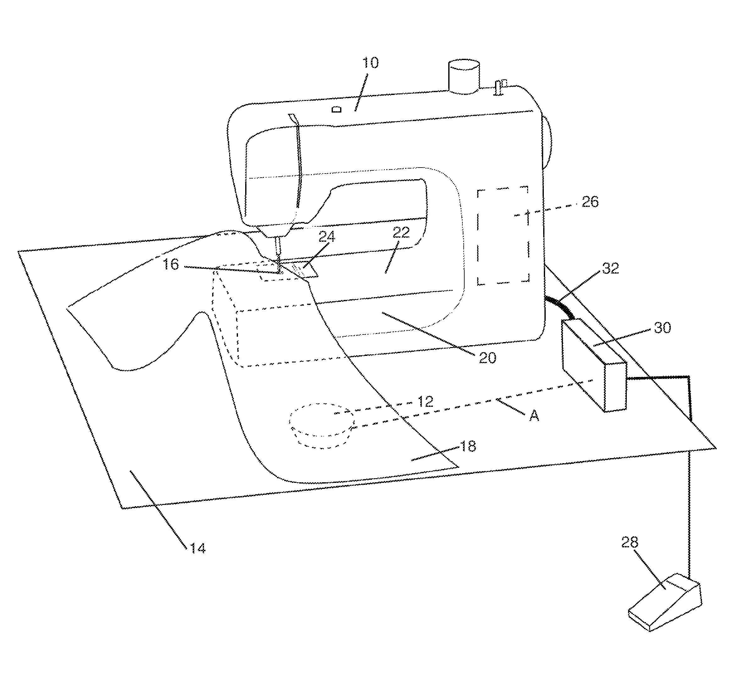
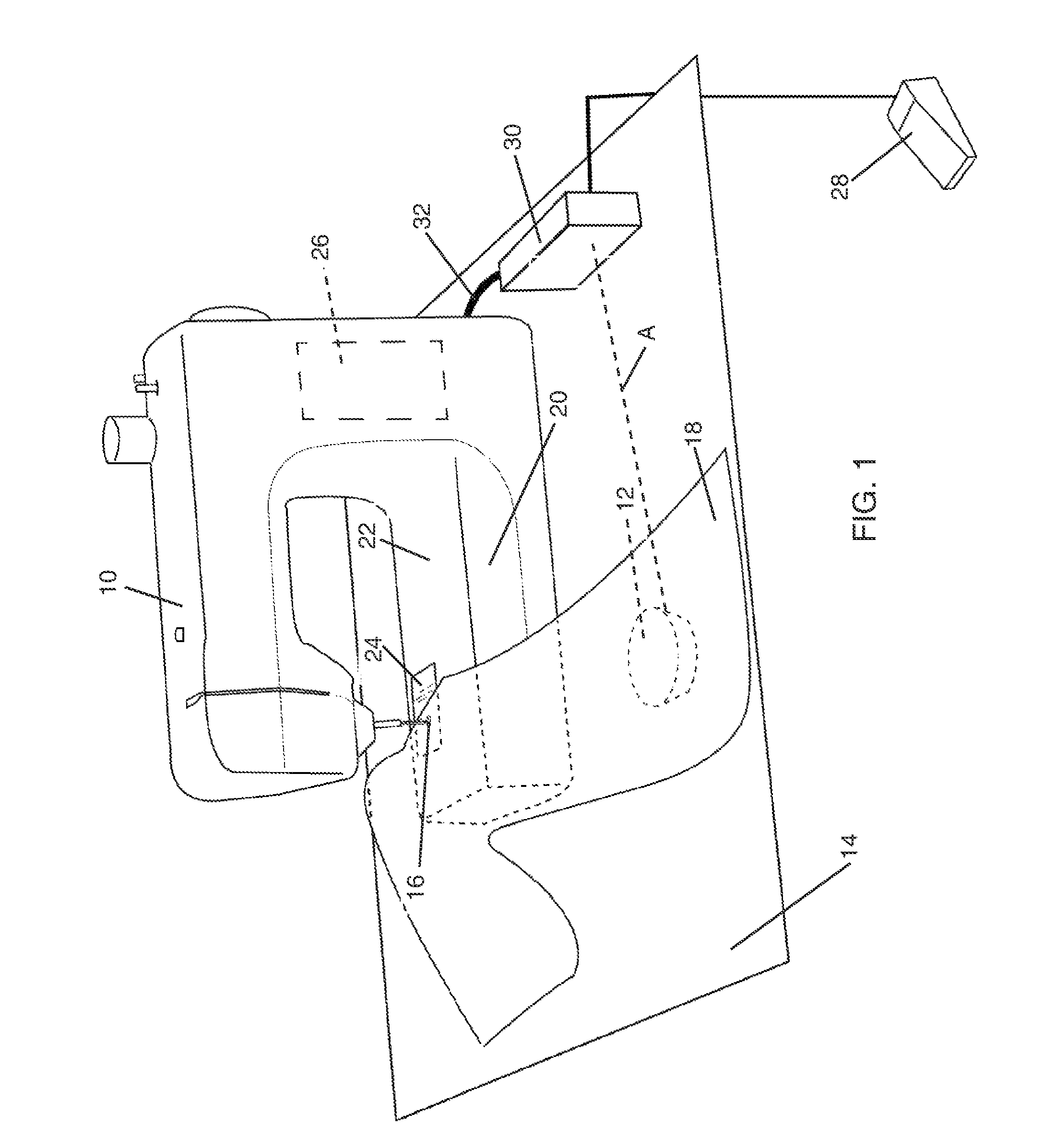
[0027]FIG. 1 shows a perspective view of one preferred embodiment using a sewing machine 10 with a movable detection device 12 for controlling and / or regulating the movement of the sewing needle. Stitching is controlled by detecting relative movement of the movable detection device 12 placed against a stationary reference surface 14 and communicating relative movement information to the sewing ma...


PUM


Abstract

A device controls the speed of needle movement in a sewing machine and thus the stitch length based upon the movement of a motion detection device relative to a reference surface. The formation of stitches by the sewing machine is controlled by detected changes in position of the detection device relative to the reference surface in connection with a predetermined stitch length setting and starting speed, set on either the detection device, an adapter or as part of the sewing machine control. The detection device may move together with the article being sewn while the sewing machine and reference surface remain stationary, or the detection device may move with the sewing machine while the article that is being sewn and reference surface remain stationary.

Description

RELATED APPLICATION[0001]This application claims the benefit of U.S. Provisional Patent Application Ser. No. 61 / 469,316 that was filed on Jun. 13, 2011, for an invention titled METHOD AND DEVICE FOR CONTROLLING STITCHING USING A MOVABLE SENSOR, which is herein incorporated by this reference.TECHNICAL FIELD[0002]The present invention relates generally to controlling quilting and sewing machines. More specifically, the present invention relates to controlling stitching using a movable sensor.BACKGROUND[0003]Free motion sewing, also called free motion quilting, is performed by an operator with a sewing machine set up with the material transportation device (e.g., feed dogs) in the lower arm of the sewing machine, disabled or non-existent. This allows sewing in any direction the material may move. Stitch length is then controlled by the operator depressing a standard foot control (such as a treadle starter) and moving the material under the needle at a rate which will create the desired...

Claims


Application Information

Patent Timeline
Patent Type & Authority Patents(United States)
IPC IPC(8): D05B1/00D05B21/00D05B19/12
CPCD05B19/12D05B21/00
Inventor KONZAK, GARY J.EICH, RICHARD K.RUGGLES, BRYAN K.
Owner HANDI QUILTER
Why Eureka
Try Eureka