Method of manufacturing flexible piezoelectric energy harvesting device

a piezoelectric energy harvesting and flexible technology, applied in the direction of piezoelectric/electrostrictive transducers, device material selection, transducer types, etc., can solve the problems of complex manufacturing process, limited piezoelectric substances, and functional parts of organic thin films that cannot ensure high performance, etc., to achieve high efficiency and simplify the manufacturing process

Inactive Publication Date: 2015-08-25
KOREA INST OF SCI & TECH
View PDF9 Cites 20 Cited by
  • Summary
  • Abstract
  • Description
  • Claims
  • Application Information

AI Technical Summary

Benefits of technology

[0027]Therefore, by implementing a flexible piezoelectric energy harvesting device using a piezoelectric composite layer produced by mixing piezoelectric powder with polymer, it is possible to simplify a manufacturing process and manufacture a highly efficient flexible piezoelectric energy harvesting device having various sizes and patterns. Also, the flexible piezoelectric energy harvesting device can be formed with various kinds of piezoelectric materials so that a wide range of applications can be expected.

Problems solved by technology

However, a functional part of an organic thin film cannot ensure high performance due to the properties of an organic thin film, and piezoelectric substances are limited.
Also, the technology of transferring an inorganic thin film has problems of making a manufacturing process complicated, not maintaining constant yield, and laying limitations on the selection of inorganic substances usable.
However, a functional part of an organic thin film cannot ensure high performance due to the properties of an organic thin film, and piezoelectric substances are limited.
Also, a technology of transferring an inorganic thin film has problems of making a manufacturing process complicated, not maintaining constant yield, and laying limitations on the selection of inorganic substances usable.
In addition, in the case of the method of manufacturing the flexible device using the composite produced by mixing NaNbO3 nanowires with PDMS, a manufacturing process of the nanowires is complicated, which makes mass-production difficult.

Method used


Image

  • Method of manufacturing flexible piezoelectric energy harvesting device
  • Method of manufacturing flexible piezoelectric energy harvesting device
  • Method of manufacturing flexible piezoelectric energy harvesting device

Examples


example

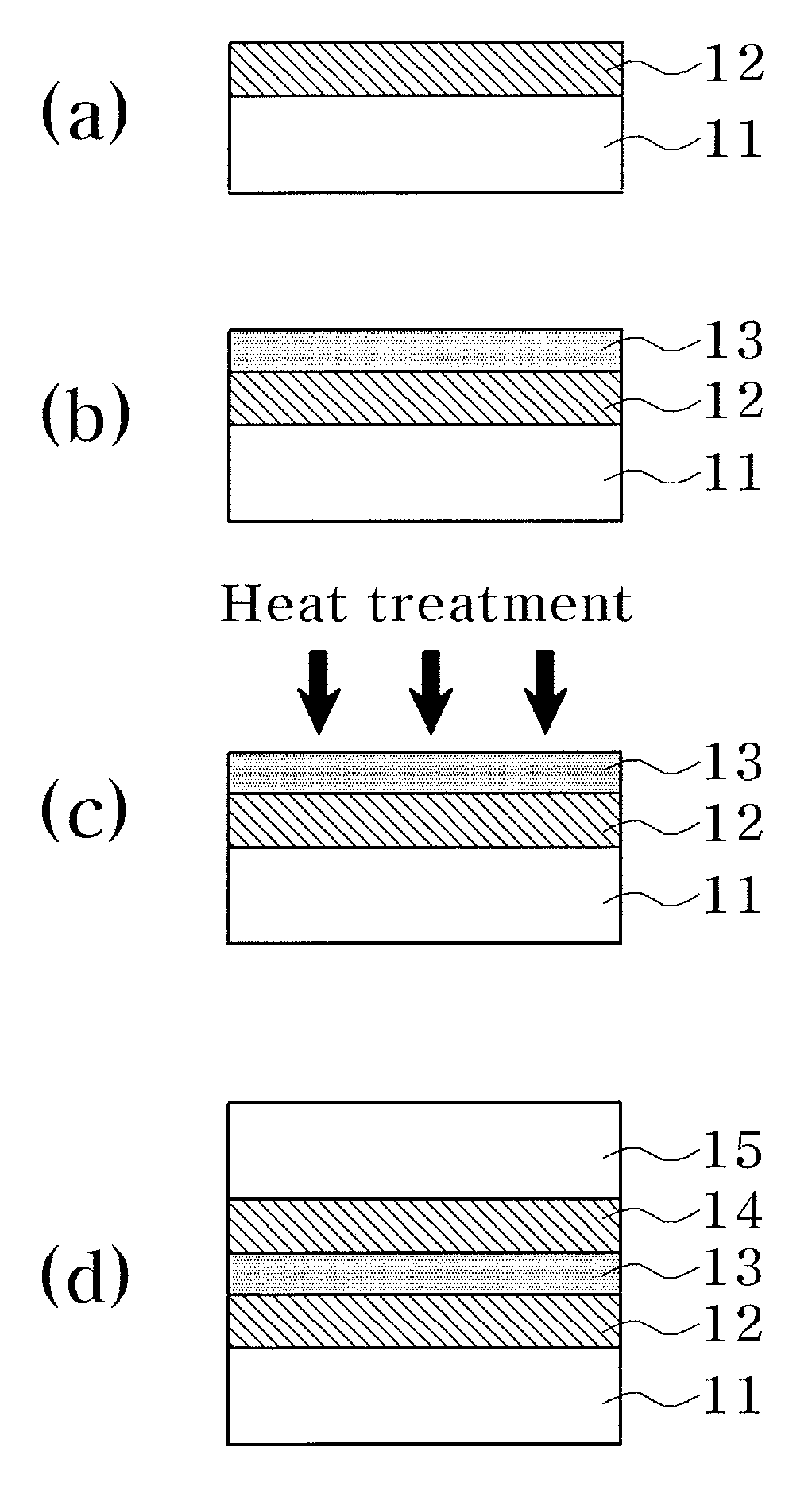
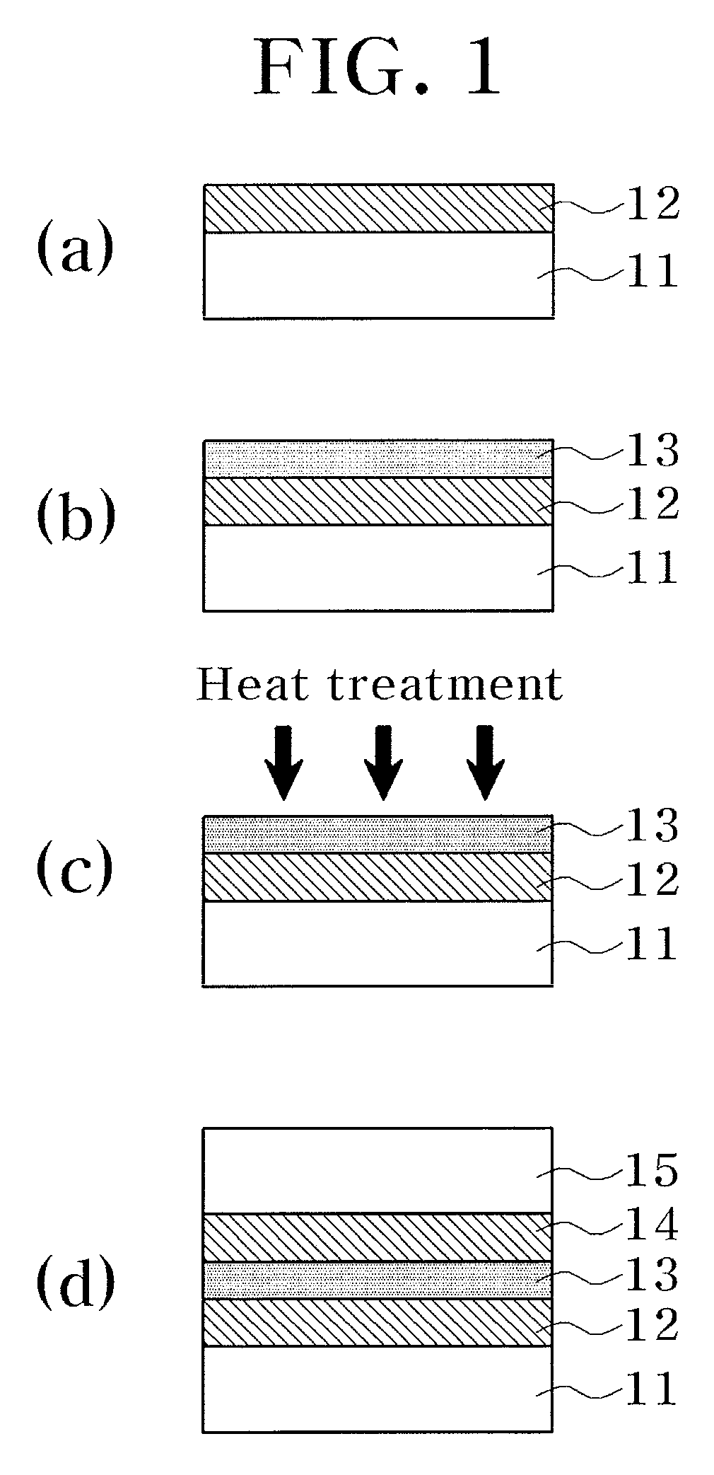
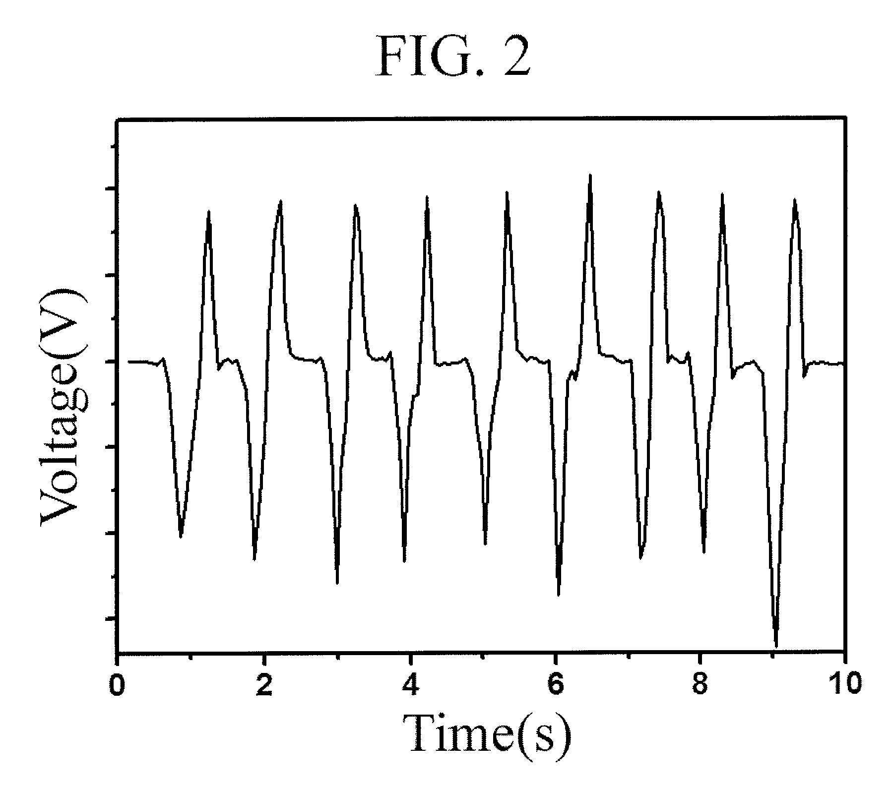
[0052]A Pt electrode layer was formed on a polyimide-based flexible substrate. The Pt electrode layer was formed at room temperature to a thickness of 100 nm using a PVD method. Successively, a mixture produced by mixing 1 g of PZT with 12 g of PDMS was deposited to a thickness of 10 μm on the Pt electrode layer by a spin-coating method to thereby form a piezoelectric composite layer, wherein the average particle diameter of the PZT was 20 nm. Thereafter, heat treatment was performed for 12 minutes in an oven at 80° C. to harden the piezoelectric composite layer. Then, a polyimide-based flexible substrate with a Pt electrode layer was bonded on the piezoelectric composite layer to thereby manufacture a flexible piezoelectric energy harvesting device. The Pt electrode layer on the polyimide-based flexible substrate was formed to a thickness of 100 nm at room temperature by a PVD method. The results of measurement on the output voltage of the flexible piezoelectric energy harvesting d...


PUM

PropertyMeasurementUnit
particle diameteraaaaaaaaaa
temperatureaaaaaaaaaa
thicknessaaaaaaaaaa

Abstract

Provided are a method of manufacturing a flexible piezoelectric energy harvesting device using a piezoelectric composite, and a flexible piezoelectric energy harvesting device manufactured by the same. The method of manufacturing the flexible piezoelectric energy harvesting device includes: forming a first electrode layer on a first flexible substrate; spin-coating a piezoelectric composite layer on the first electrode layer, wherein the piezoelectric composite layer is produced by mixing piezoelectric powder with polymer; performing heat treatment on the piezoelectric composite layer to harden the piezoelectric composite layer; and bonding a second flexible substrate with a second electrode layer on the hardened piezoelectric composite layer. Therefore, it is possible to simplify a manufacturing process and manufacture a high-performance flexible piezoelectric energy harvesting device having various sizes and patterns.

Description

CROSS-REFERENCE TO RELATED APPLICATION[0001]This application claims priority to and the benefit of Korean Patent Application No. 2012-0063206, filed on Jun. 13, 2012, the disclosure of which is incorporated herein by reference in its entirety.BACKGROUND[0002]1. Field of the Invention[0003]The present invention relates to a method of manufacturing a flexible piezoelectric energy harvesting device using a piezoelectric composite and a flexible piezoelectric energy harvesting device manufactured by the same, and more particularly, to a method of manufacturing a flexible piezoelectric energy harvesting device using a piezoelectric composite layer produced by mixing piezoelectric powder with polymer, and a flexible piezoelectric energy harvesting device manufactured by the method.[0004]2. Discussion of Related Art[0005]With the rapid development of electronic technologies in the past decade, device miniaturization and power consumption reduction are being accelerated. In order to develop...

Claims


Application Information

Patent Timeline
Patent Type & Authority Patents(United States)
IPC IPC(8): H01L41/22H04R17/00H01L41/113H01L41/18H01L41/312H01L41/317
CPCH01L41/113H01L41/183H01L41/312H01L41/317Y10T29/42H10N30/30H10N30/077H10N30/092H10N30/80H10N30/01H10N30/072H10N30/852
Inventor KANG, CHONG YUNYOON, SEOK JINDO, YOUNG HOCHOI, JI WONSONG, HYUN CHEOLBAEK, SEUNG HYUBKIM, JIN SANG
Owner KOREA INST OF SCI & TECH
Why Eureka
Try Eureka