System and methods for cooling electronic equipment

a technology of electronic equipment and cooling system, which is applied in the direction of electrical equipment contruction details, refrigeration components, lighting and heating apparatus, etc., can solve the problems of reducing the safety of limiting parameters of compressors, requiring tight temperature and humidity control of compressors using modern-day inverters (e.g., motor speed controllers or variable speed drives), and rarely controlling humidity within these spaces. , to achieve the effect of stable or closer tolerance of pumped fluid, and reducing the safety o

Active Publication Date: 2015-08-25
INERTECH IP
View PDF14 Cites 45 Cited by
  • Summary
  • Abstract
  • Description
  • Claims
  • Application Information

AI Technical Summary

Benefits of technology

[0015]The systems and methods according to the present disclosure utilize stable temperate-pumped cooling fluid from an external source (independent circuit) to cool the compressor motor inverters on either single compressors or chiller compressors that are operating on another independent circuit. The systems and methods according to the present disclosure could be modified to be used on many complementary systems that utilize a relatively stable or closer tolerance pumped fluid, e.g., water or refrigerant, to be pumped to cool a fluctuating compressed circuit inverter. The systems and methods according to the present disclosure not only may enable the safety “span” or limiting parameters of the compressors to be reduced, but also may remove the need for other limiting sensors that are typically included on the systems as protective devices.
[0016]The data center IT cooling industry has adopted the use of pumped refrigerant as a means to cool many data centers. As a result, there are pumped refrigerant systems that deliver temperate liquid refrigerant to the evaporator side (or load side) of the system in close proximity to compressed refrigeration circuits that are on the heat rejection side of the system. The systems and methods according to the present disclosure utilize a small portion of pumped refrigerant from the liquid system and deliver it in close temperature and flow rates to the motor inverter on the compressed cooling circuits. By utilizing this fluid, which would not normally be used for this purpose, the systems and methods according to the present disclosure are able to provide the inverter a stable temperate flow in very close tolerances. The ability to provide the inverter with such close tolerance “optimum” fluid temperatures enables the compressor manufacturer to remove many of the “limiting” safety parameters that have been included both in the software as well in some cases hard wired limiting devices with restrictive set points.
[0034]In some embodiments, mechanically cooling the first fluid includes cooling the first fluid in the fluid receiver by enabling heat transfer from the first fluid in the fluid receiver to a third fluid, compressing the third fluid, condensing the compressed third fluid by enabling heat transfer from the compressed third fluid to the second fluid that has been cooled using atmospheric air, and reducing the pressure of the condensed third fluid to reduce the temperature of the third fluid.

Problems solved by technology

Compressors using modern-day inverters (e.g., motor speed controllers or variable speed drives) require very tight temperature and humidity control.
Various manufacturers of compressors and chillers have experienced many problems with maintaining tight control of this cooling process because of the variables associated with the cooling media, as well as the environmental variables or conditions of the space in which the inverter operates.
These spaces are rarely cooled and the humidity within these spaces is rarely controlled.
The confluence of these two influences—media temperature and environmental conditions—presents certain challenges.
It is this tight control issue that has stymied many manufacturers and presented problems with safety and limit controls that need to be employed in order to protect the equipment during less than advantageous operating conditions.
The problem with these systems, however, is that they are inherently inefficient systems.
In addition, they limit and / or prevent operation of the motors at higher performance conditions if those conditions create a situation where the inverter could potentially be damaged or fail due to the influence of the outside variables.
This could create condensation, which could potentially damage the inverter or create a “short circuit” or grounding problem.
To avert these problems, chillers or compressors include dew point safety sensors that sense harmful levels of condensation and safety limit devices that reduce the amount of cooling water supplied to the inverter if the dew point safety sensors sense harmful levels of condensation.
As a result, the inverter would heat up and the inverter's heat sensors would cause the motor output to slow down or stop altogether.
These safety and limiting features protect the motor inverter, but they also limit the chiller output capacity at a critical point in the chiller efficiency operating curve.
This means that the compressor cannot continue to operate or operate at higher capacity at the most opportune operating condition for the chiller.
These safety and limiting features severely impede the compressor from operating over a greater span of water, refrigerant, and ambient temperatures.
The safety and limiting features also severely limit a chiller's ability to enter into and out of free cooling in a seamless manner.
This was mainly due to a concern for condensate and the resultant damage that could occur.
In some embodiments, mechanically cooling the second fluid includes mechanically cooling the second fluid to the extent that free cooling the first fluid is insufficient to cool the first fluid.

Method used


Image

  • System and methods for cooling electronic equipment
  • System and methods for cooling electronic equipment
  • System and methods for cooling electronic equipment

Examples


Embodiment Construction

[0057]Embodiments of the presently disclosed close-coupled cooling systems and methods will now be described in detail with reference to the drawings, in which like reference numerals designate identical or corresponding elements in each of the several views.

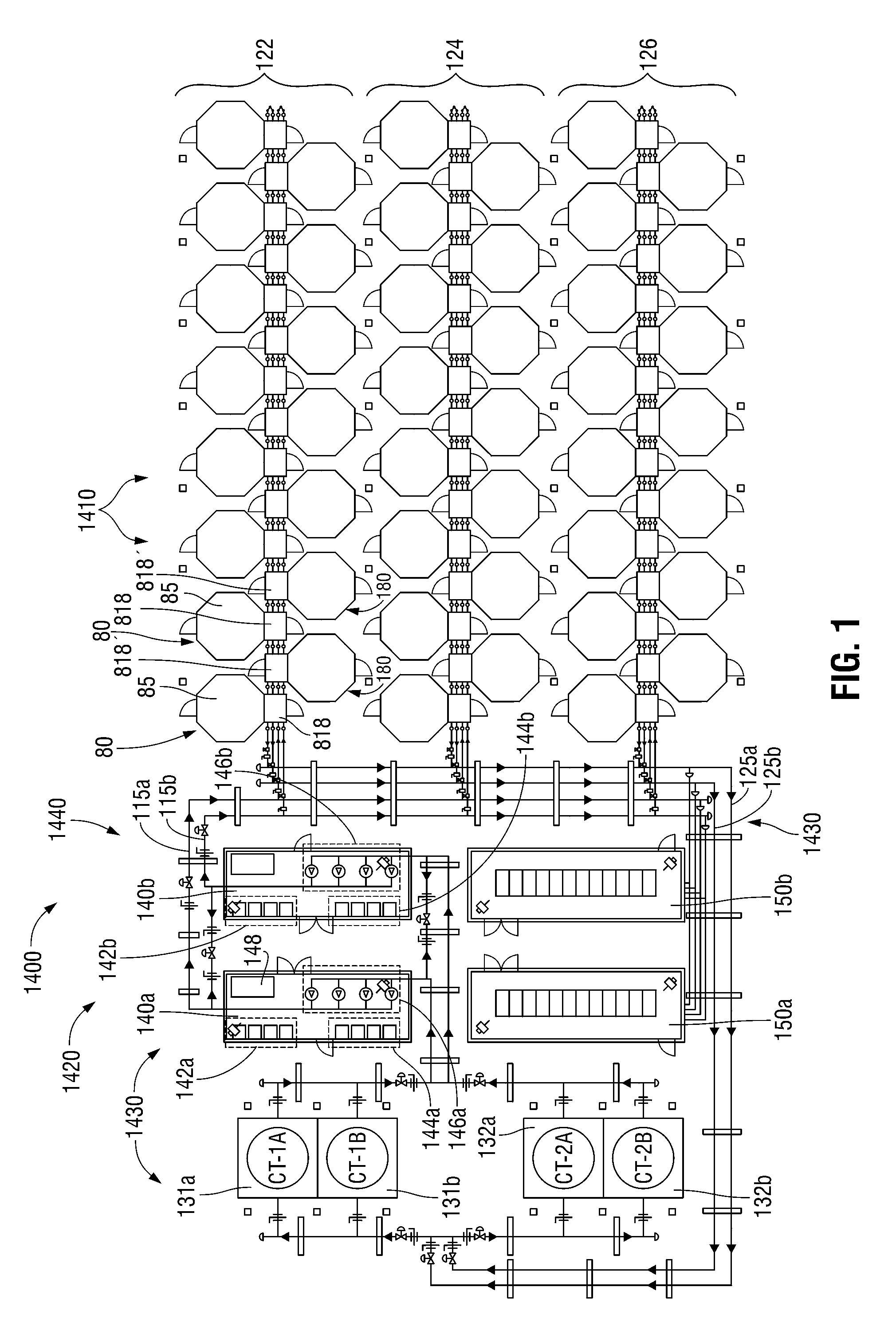
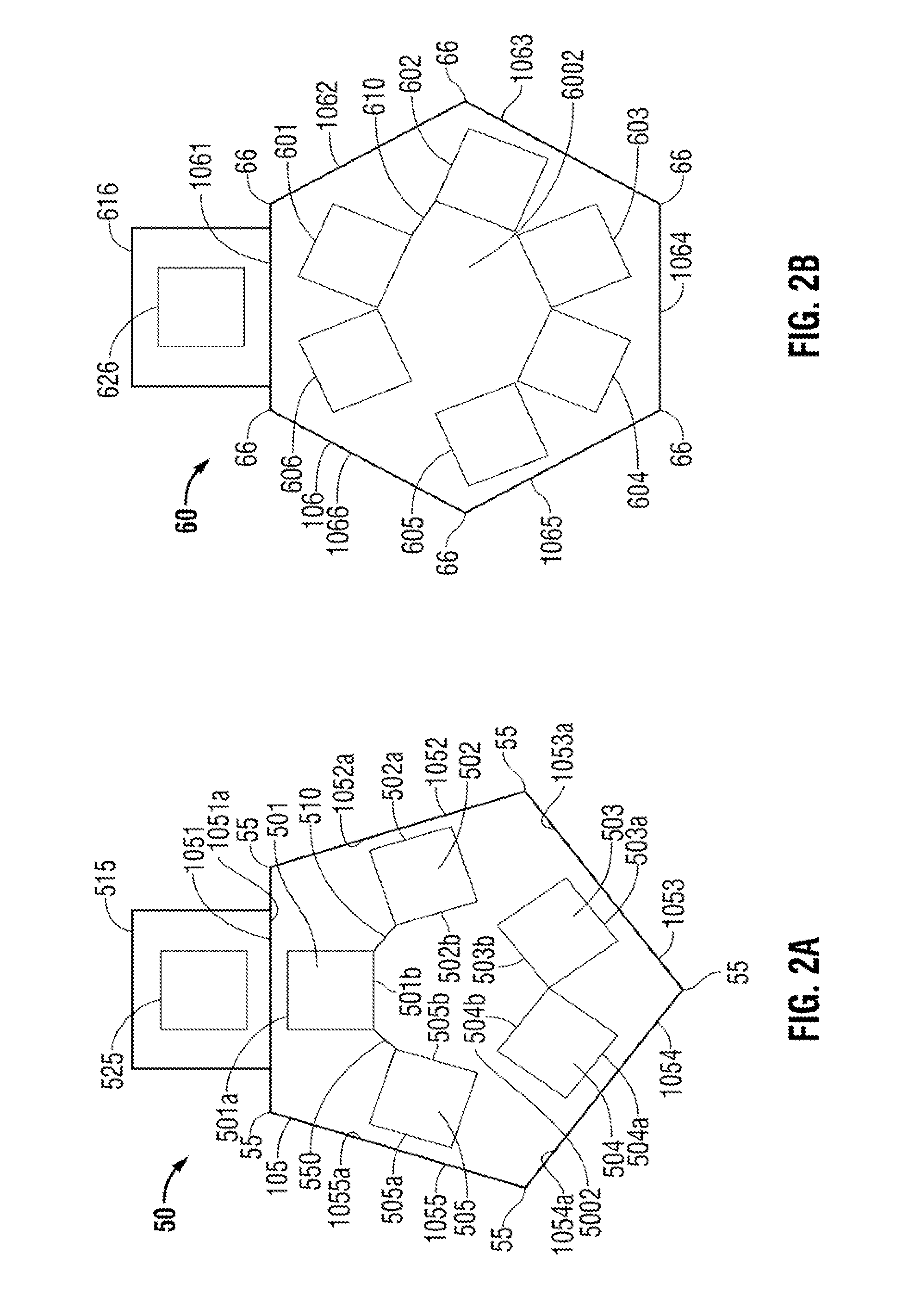
[0058]The present disclosure relates to modular data pods and related support systems for providing energy-efficient, space-saving, and high-density server rack configurations. This modular approach allows for highly efficient use of geometric shapes such as octagonal, hexagonal, and pentagonal shapes for creating a hot aisle and a cold aisle through which air circulates for cooling the server racks. These polygonal shapes allow for maximum energy-efficiency and space-savings using the benefits of both the interior and the exterior angles and sides. The interior pod shape provides a natural circular configuration for positioning server racks. As compared to the prior art, this configuration provides a more efficient way to creat...


PUM

PropertyMeasurementUnit
temperaturesaaaaaaaaaa
inlet temperaturesaaaaaaaaaa
temperatureaaaaaaaaaa

Abstract

Systems and methods for cooling an inverter of a variable frequency drive that drives a compressor in a cooling system for electronic equipment are disclosed. The system includes a first fluid circuit that cools electronic equipment using a first fluid flowing therethrough and a second fluid circuit that free cools a second fluid flowing therethrough. The second fluid circuit cools the first fluid using the free-cooled second fluid. The system further includes a third fluid circuit that mechanically cools the second fluid using a third fluid flowing therethrough as a function of the wet bulb temperature of atmospheric air. The third fluid circuit includes at least one compressor compresses the third fluid and is driven by a motor coupled to the variable frequency drive. At least a portion of the first fluid flowing through the third fluid circuit is diverted to cool the inverter of the variable frequency drive.

Description

CROSS REFERENCE TO RELATED APPLICATIONS[0001]This application is a national phase of International Application No. PCT / US2012 / 037858 filed on May 14, 2012 and claims the benefit of, and priority to, U.S. Provisional Application No. 61 / 486,049, which was filed on May 13, 2011, the entire contents of each of which are incorporated by reference herein.BACKGROUND[0002]1. Technical Field[0003]The present disclosure generally relates to cooling systems for electronic equipment. More particularly, the present disclosure relates to systems and methods for cooling inverters of variable frequency drives in cooling systems for electronic equipment.[0004]2. Background of Related Art[0005]Compressors are deployed for many air conditioning and refrigeration systems including for commercial and industrial cooling for human comfort and refrigeration applications including systems for cooling data centers. Compressors using modern-day inverters (e.g., motor speed controllers or variable speed drives...

Claims


Application Information

Patent Timeline
Patent Type & Authority Patents(United States)
IPC IPC(8): H05K7/20F25B31/00
CPCH05K7/2029F25B31/006H05K7/20745H05K7/20827F25B2600/021Y02B30/741Y10T29/49359Y02B30/70H05K7/20327H05K7/20381
Inventor MCDONNELL, GERALDKEISLING, EARLCOSTAKIS, JOHN
Owner INERTECH IP
Why Eureka
Try Eureka