Ultrasonic testing device having an adjustable water column

a technology of ultrasonic testing and water column, which is applied in the field of ultrasonic inspection, can solve the problems of inability to assess failure or degradation of installed adhesive bonded structures, and failure of the overall quality of the composite structure, so as to improve the sensitivity of conventional a-scan, improve the sensitivity, and improve the quality of the overall structur

a technology of ultrasonic testing and water column, which is applied in the field of ultrasonic inspection, can solve the problems of inability to assess failure or degradation of installed adhesive bonded structures, and failure of the overall quality of the composite structure, so as to improve the sensitivity of conventional a-scan, improve the sensitivity, and improve the quality of the overall structur

US9121817B1Active Publication Date: 2015-09-01NAT TECH & ENG SOLUTIONS OF SANDIA LLC

Image

  • Ultrasonic testing device having an adjustable water column
  • Ultrasonic testing device having an adjustable water column
  • Ultrasonic testing device having an adjustable water column

Examples


Embodiment Construction

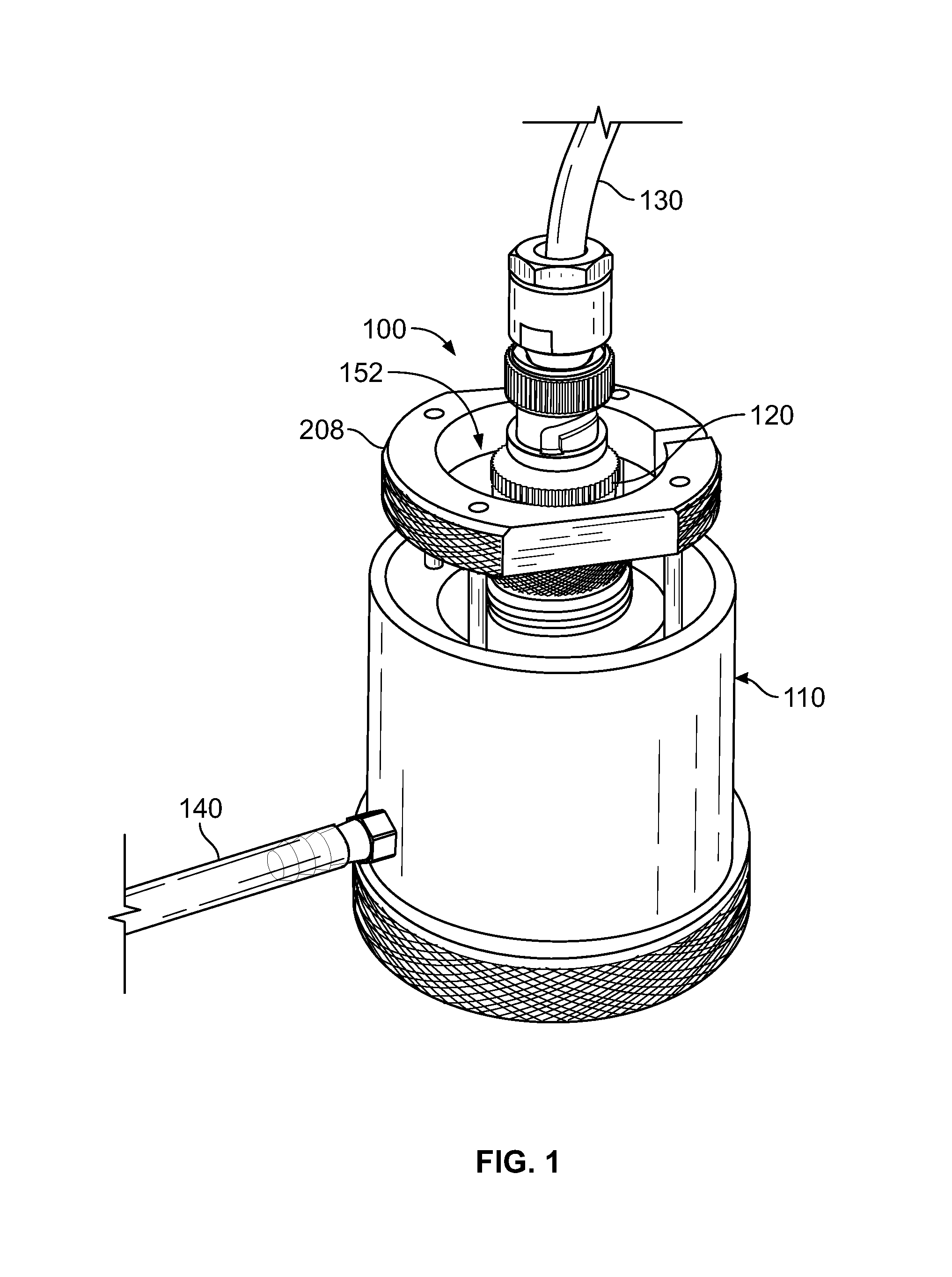
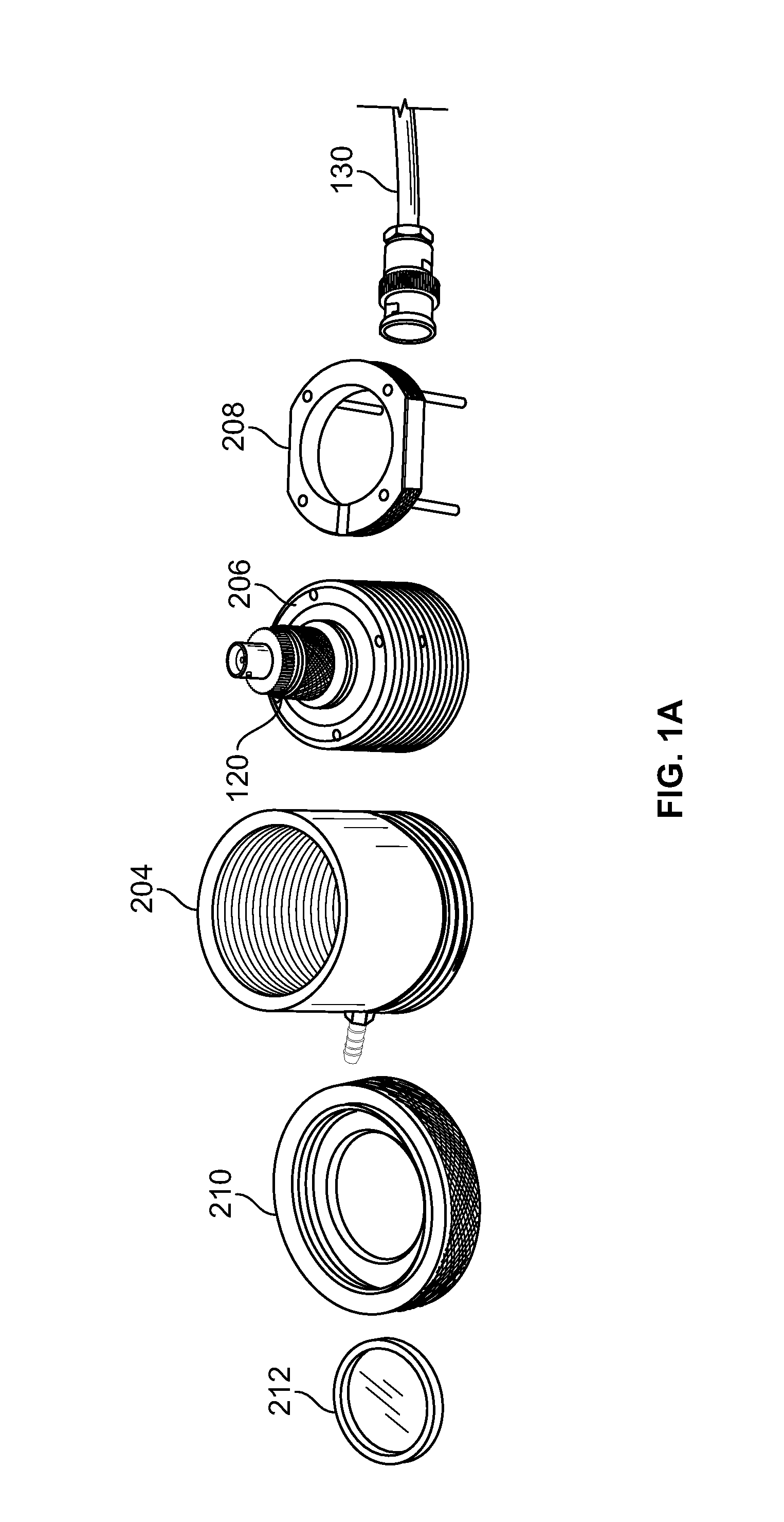
[0038]FIGS. 1 and 1A illustrate an ultrasonic testing (UT) device 100 according to the present invention. As can be seen in FIG. 1, the UT device 100 includes a housing system 110, a transducer 120 attached to the housing system 110, a signal transmission link 130 coupled to the transducer 120, and a fluid line 140 coupled to the housing system 110. The UT device further includes an optional height control device 208. The UT device 100 is disposed or positioned upon an inspection surface 150 of a test article 160 (see FIG. 5).

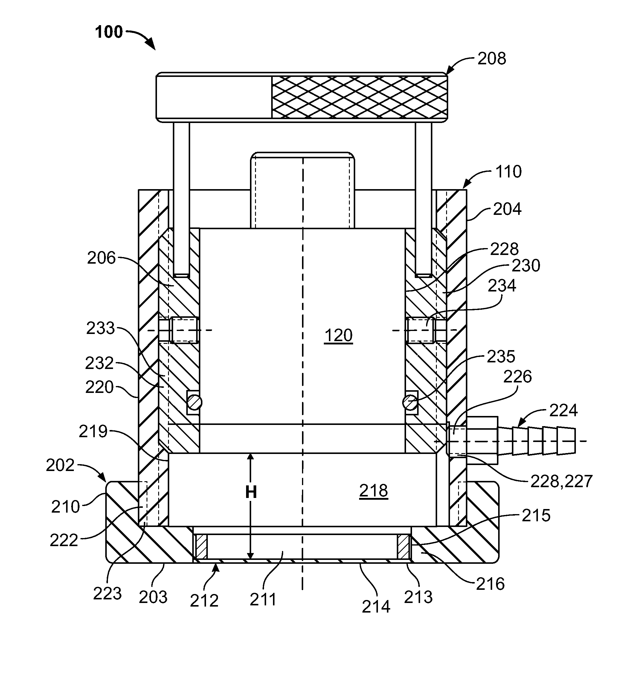
[0039]FIG. 2 shows a cross-sectional view of the UT device 100 of FIG. 1. As can be seen in FIG. 2, the housing 110 includes a scanning shoe 202, an outer housing 204, an inner housing 206, and a height adjustment control device 208. The scanning shoe 202 includes a base 210 and a flow control device 212. The base 210 includes a bottom surface 203 having an opening 211. The base 210 provides alignment of the housing 100 in relationship to the test article 160 (...


PUM

PropertyMeasurementUnit
frequenciesaaaaaaaaaa
heightaaaaaaaaaa

Abstract

An ultrasonic testing device having a variable fluid column height is disclosed. An operator is able to adjust the fluid column height in real time during an inspection to to produce optimum ultrasonic focus and separate extraneous, unwanted UT signals from those stemming from the area of interest.

Description

CROSS-REFERENCE TO RELATED APPLICATIONS[0001]This application is a nonprovisional of U.S. Provisional Patent Application 61 / 660,264, filed Jun. 15, 2012, entitled “Ultrasonic Testing Device Having an Adjustable Water Column, the disclosure of which is incorporated by reference in its entirety.[0002]This application is related to U.S. patent application Ser. No. 13 / 237,520, filed Sep. 20, 2011, entitled “Ultrasonic Probe Deployment Device for Increased Wave Transmission and Rapid Area Scan Inspections”, which is a Continuation of application Ser. No. 12 / 401,321, filed Mar. 10, 2009, now allowed, entitled “ULTRASONIC PROBE DEPLOYMENT DEVICE FOR INCREASED WAVE TRANSMISSION AND RAPID AREA SCAN INSPECTIONS”, and U.S. Pat. No. 6,234,025, filed Mar. 29, 1999, entitled ULTRASONIC INSPECTION APPARATUS AND METHOD USING A FOCUSED WAVE DEVICE”, whose disclosures are incorporated by reference in their entirety.STATEMENT REGARDING FEDERALLY SPONSORED RESEARCH OR DEVELOPMENT[0003]The United States...

Claims


Application Information

Patent Timeline
01 Sep 2015
Publication
US9121817B1
IPC
G01N29/28
CPC
G01N29/28; G01N29/07; G01N29/11; G01N29/48; G01N2291/0231; G01N2291/0258
Inventors
ROACH, DENNIS P.; NEIDIGK, STEPHEN O.