LED dimming device and LED dimming and driving circuit

a technology of led dimming and driving circuit, which is applied in the direction of electric variable regulation, process and machine control, instruments, etc., can solve the problems of unstable dimming via a silicon controlled rectifier dimmer, nonsine waves generating serious interference signals in the circuit, and the power factor and work efficiency of the dimming device are reduced, and the harmonic coefficient and interference signal are reduced.

Active Publication Date: 2015-09-01
FREMONT MICRO DEVICES CORP
View PDF2 Cites 25 Cited by
  • Summary
  • Abstract
  • Description
  • Claims
  • Application Information

AI Technical Summary

Benefits of technology

[0013]The primary objective of the present invention is to provide a LED dimming device that not only compatible with existing illumination application circumstance but also have high efficiency, aiming at the technical problems mentioned above.
[0024]When operating, the LED dimming device and the driving circuit using such LED dimming device will not affect the sine waves of the input current, in such a way, power factor and work efficiency will be increased while the harmonic coefficient and interference signal will be reduced.

Problems solved by technology

However, problems as follows present in LED illuminations when using silicon controlled rectifier dimmer for dimming.
Moreover, the smaller the conducting angle, the worse the power factor.
3. The nonsine waves generate serious interference signals in the circuit.
4. Dimming via a silicon controlled rectifier dimmer is unstable for a small load such as a LED, and requires a bleeder resistor consuming additional power and reducing efficiency.

Method used


Image

  • LED dimming device and LED dimming and driving circuit
  • LED dimming device and LED dimming and driving circuit
  • LED dimming device and LED dimming and driving circuit

Examples


first embodiment

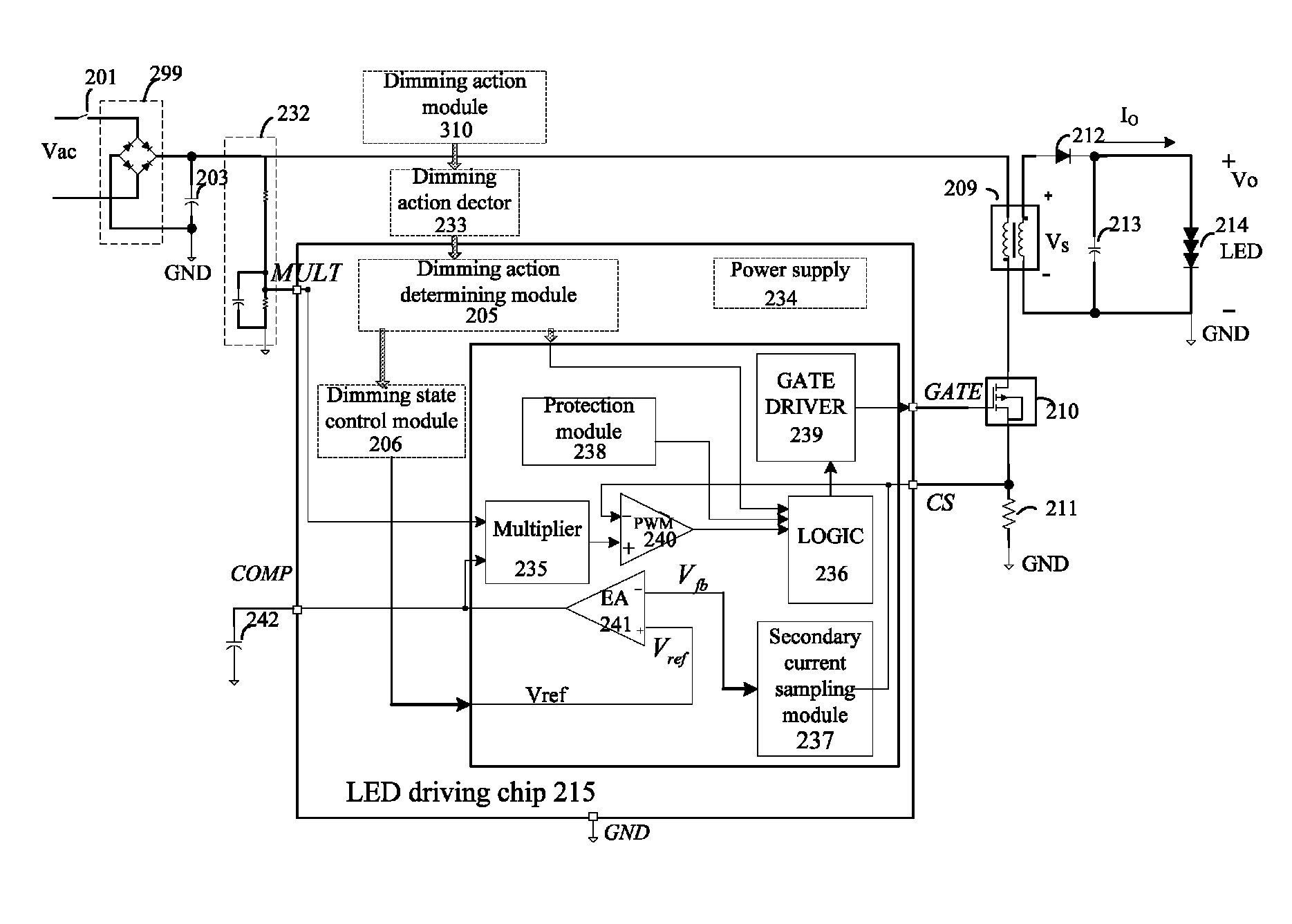
[0039]FIG. 4 shows a functional block diagram of a LED dimming device according to present invention. As shown in FIG. 4, the LED dimming device comprises a dimming action module 310, a dimming action detector 233, a dimming action determining module 205 and a dimming state control module 206. The LED dimming device is coupled to a LED driving chip 215 of the LED driving circuit. In present invention, the dimming action module 310 generates a dimming action signal. One skilled in the art knows that the dimming action module 310 can be any known triggering module, such as a switch, a key, a button and so on. In one preferable embodiment of present invention, the switch 201 of the LED driving circuit is multiplexed as dimming action module 310. The dimming action detector 233 receives the dimming action signal from the dimming action module 310, and generates a dimming instruction voltage based on the dimming action signal. One skilled in the art knows that, the dimming action detecto...

second embodiment

[0041]FIG. 5 shows a functional block diagram of a LED dimming device according to present invention. As shown in FIG. 5, the LED dimming device is coupled into the LED driving chip 215 of the LED driving circuit. In present embodiment, the LED dimming device according to present invention comprises a dimming action module 310, a dimming action detector 233, a dimming action determining module 205 and a dimming state control module 206. In present embodiment, the switch 201 of the LED driving circuit is multiplexed as dimming action module 310, the sampling module 232 of the LED driving circuit can be multiplexed as the dimming action determining module 233. As shown in FIG. 5, the inputting switch 201 is connected between an AC input terminal and a rectification module 209 of the LED driving circuit. In present embodiment, the sampling module 232 comprises a first sampling resistor, a second sampling resistor and a sampling capacitor. Wherein, the first sampling resistor and the se...


PUM


Abstract

A LED dimming device, and a LED dimming and a driving circuit using such LED dimming device are discussed. In present embodiment, the LED dimming device multiplexes an inputting switch and / or a sampling module of the LED driving circuit for dimming. such LED dimming device will not affect the sine waves of input current, in such a way, power factor and work efficiency will be increased while the harmonic coefficient and interference signal will be reduced.

Description

CROSS-REFERENCE TO RELATED APPLICATIONS[0001]This non-provisional application claims priority under 35 U.S.C. §119(a) on Patent Application No. 201210064668.3 filed in P.R. China on Mar. 13, 2012, the entire contents of which are hereby incorporated by reference.FIELD OF THE INVENTION[0002]The present invention relates to Low Emitting Diode (LED) lighting field, and more particularly relates to a LED dimming device, and a LED dimming and a driving circuit using such LED dimming device.BACKGROUND OF THE INVENTION[0003]Silicon controlled rectifier dimmers are generally used by common incandescent lamps and halogen lamps for dimming. Silicon controlled rectifier dimmers alter the effective current value of the AC current through changing the conduction angle, so as to dim the incandescent lamps and halogen lamps.[0004]FIG. 1 shows a block diagram of an exemplary prior-art silicon controlled rectifier dimmer 227. In such a silicon controlled rectifier dimmer 227, a RC network comprising...

Claims


Application Information

Patent Timeline
Patent Type & Authority Patents(United States)
IPC IPC(8): H05B33/08H05B37/02H05B39/04H05B41/36G05F1/00H05B44/00
CPCH05B33/0845H05B45/10H05B45/382Y02B20/30
Inventor LIAO, WEIMINGKU, MATTHEW MAN HOZHENG, YUEGUO, LIFANGYOU, GUANGYAO
Owner FREMONT MICRO DEVICES CORP
Why Eureka
Try Eureka